Looks good. Just a couple of comments:
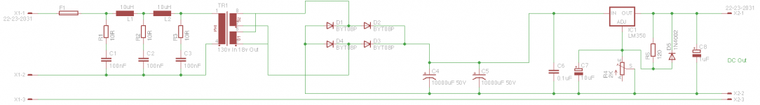
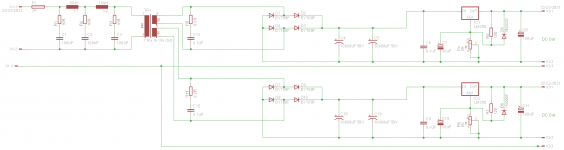
Nice touch to snubber the primary - but make sure the caps are rated for the PEAK value! Probably easier to snubber at the secondary though, you get some free attenuation from the transformer.
What current should this provide? 2 x 10kuF seems excessive and will result in quite high-and-short charge current pulses with lots of harmonics.
In the regulator you use the pot as a rheostat. That's fine but I would connect the bottom pin to the wiper. That way, if the wiper fails, it will not be open.
jan
Hi Jan
It needs to put out about 3 amps at 12v.
To be honest I just happen to have the 10KuF Caps so thought I'd use them!
What would you recommend?
I'll connect the wipper as suggested.
I assume when you say 'snubber' you mean the mains filter before the primary? Should I just move all of that over to the secondaries?
Many Thanks
Neil
Last edited:
You could usefully put a snubber across the secondary, perhaps 0.1uf and 2.2 ohm. Keep the primary ones.
Large reservoir caps is one my concerns in many many designs. I did a brief explanation only this morning, post #12,
http://www.diyaudio.com/forums/chip-amps/228860-stk4044-power-up.html#post3362294
Large reservoir caps is one my concerns in many many designs. I did a brief explanation only this morning, post #12,
http://www.diyaudio.com/forums/chip-amps/228860-stk4044-power-up.html#post3362294
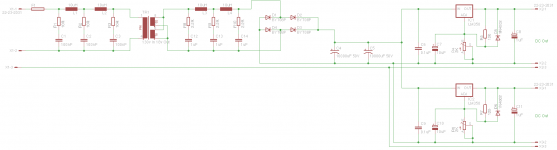
If each separate secondary can supply the needed amperage, you could duplicate the snubber and bridge and everything after. Paralleling the secondary as shown saves parts and real estate. I'm not sure it makes significant difference either way; separation may have the edge if the loads are wildly different.
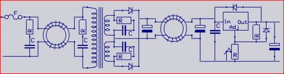
Perhaps something like this ") I don't no if all that snubbering has much use.
I don't no if all that snubbering has much use.
By using two diodes there is less loss and thereby less heat from the rectifiers.With the currents in the same direction in the toroidals there is no saturaion of the core,more inductance left.
Why KµF ,for a meter you don't use Kmm do you.So KµF is simply mF .
Mona
I don't no if all that snubbering has much use.By using two diodes there is less loss and thereby less heat from the rectifiers.With the currents in the same direction in the toroidals there is no saturaion of the core,more inductance left.
Why KµF
,for a meter you don't use Kmm do you.So KµF is simply mF .Mona
Attachments
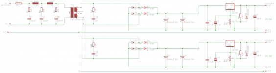
So...Like This???
Use just one set of R/C for the secondary snubber. A 0.1uf (100nF) and 2.2 ohm. No coils on the secondary side
Yes, Mooly's right. You only need change the connections at the transformer secondaries.
You're fast.
You should calculate the resistance needed at the regulators' adjust pin and change that potentiometer to a fixed value. Unless you have some need to vary the voltages to your amps.
You're fast.
You should calculate the resistance needed at the regulators' adjust pin and change that potentiometer to a fixed value. Unless you have some need to vary the voltages to your amps.
Last edited:
- Status
- This old topic is closed. If you want to reopen this topic, contact a moderator using the "Report Post" button.
- Home
- Amplifiers
- Power Supplies
- Is this Gonna Work?!?