I've been looking at building a Benthtop PSU and found that you can buy very cheap DC-DC converters based on the LM2596 chip. They take up to 40v input and can output anything from about 1.5 - 37V at a couple of amps.
Here are a few links:
LM2596 Mini DC-DC Step Down Adjustable Power Supply Module | eBay
LM2596 DC-DC Converter Board Voltage Regulator Stepdown Module Built in LM2596S | eBay
New LM2596 DC Buck Step-Down Voltage Adjustable Converter Power Module Regulator | eBay
This one looks interesting:
LED Voltage and current display LM2596 DC-DC Step Down CC-CV Adjust Power Supply | eBay
OK, now time for my question.....
If I want to make a dual output power supply that I can connect in series to give me a +/- DC voltage, for testing OpAmp circuits etc, can I use two of these DC-DC converters? I was thinking it would work, as long as I use a dual secondary mains transformer and feed each DC-DC converter from a different winding.
Any thoughts?
Just reading a bit more about the first link I posted:
LM2596 Mini DC-DC Step Down Adjustable Power Supply Module | eBay
It goes on mostly about constant current and charging batteries or using it as an LED driver. Could this simply be used as a PSU with current limiting feature. All you would have to do then is buy a digital 7 segment, 3 digit Volt/Ammeter and you have a very cheap PSU (except for the mains transformer that is).
But, can these be series wired if fed from different windings of the mains transformer, I still havn't found the answer on the internet.
Just found this web page:
SMPS, Switching Power Supply, DC Power Supply, Switching Mode Power Supply, User Manual, Service Manual about INSTALLATION, WIRING, CONNECTIONS
In fig 15, it shows 2 switched mode power supplies connected in series and they use a diode across each PSU for reverse protection. It doesn't show a centre tap in the diagram, but I assume you could tap off the centre for 0v and then have +/- volts.
For experimentation purposes, switching supplies are awful, even the professional ones: they accumulate about every flaw in the book: they generate residues, have suboptimal dynamic responses, need at least some tens of µF at the output making fast current limitation hopeless, etc.Just found this web page:
SMPS, Switching Power Supply, DC Power Supply, Switching Mode Power Supply, User Manual, Service Manual about INSTALLATION, WIRING, CONNECTIONS
In fig 15, it shows 2 switched mode power supplies connected in series and they use a diode across each PSU for reverse protection. It doesn't show a centre tap in the diagram, but I assume you could tap off the centre for 0v and then have +/- volts.
In addition, mains fed ones (this is not the case here) require Y capacitors which are a nightmare from a sensitive electronics point of view.
In short, this kind of supply should be avoided except for power electronics where they are not only useful, but indispensable.
As a lab supply, a traditional linear one is really the best, and is not that more costly compared to cheap and dirty switching types.
Thanks for the reply.
I already have a spare toroidal transformer and rectifiers etc, so would it not be worth getting a couple to make a cheap bench top supply for testing circuits?
You say about 'tens of µF' at the output, but if I wanted to use it purely to set a voltage and test some circuits, this wouldn't be a problem, would it? Currently I use 2x9v batteries and it really is a pain connecting them and regulating them if I need different voltages.
Anyway, could 2 of these be put in series to give -ve, 0 and +ve voltage supply? Is it worth spending a few pounds and making a simple DC power supply?
Thanks again for your help Elvee
I would steer clear of digital power supplies. The main reason is by way of the beast. They are either on or off. When the threshold voltage is reached, there is always an over kill. Use a linear device. They are cheap and variable. Use two windings, that will keep the two supplies separate and then you can series couple them, giving +ve and -ve supplies.
An LM317T is a good start and if more current is required feed a power transistor with the LM317.
An LM317T is a good start and if more current is required feed a power transistor with the LM317.
Thanks. I thought about using an LM317 as I have a few here, but the problem I thought with using one is the heat that is dissipated. If I feed it with say 30v, regulate it down to 5 and draw 1 amp, the 317 has to dissipate 25 watts. I suppose a large heat sink would do the job.
On my bench supply. 30 - 0 - 30 at 25Amps, I use a pair of 2SC5200 on a large heat sink per side and it works very well.
A good suggestion is to switch the supply DC to a lower level if you don't use the voltage. That will keep the dissipation down. I did build mine in 1983 and it has had one new voltage selector pot only!
A good suggestion is to switch the supply DC to a lower level if you don't use the voltage. That will keep the dissipation down. I did build mine in 1983 and it has had one new voltage selector pot only!
Hi, just quickly put a basic schematic together. I haven't put any values of components on, it's just an idea:
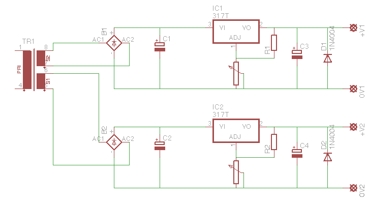
Now I know that this will give me two separate PSUs, which will be handy for when I want 2 different voltages to test with, but could I use a switch that can connect +V2 and 0V1 together to give me a +v - 0 -ve supply? If so, I think it would be good to have a 3 pos switch, 1 position would link +V2 and 0V1, the middle position would leave everything as it is and the last position would link 0V1 and 0V2 for a common 0 on both supplies. Any thoughts?
I also thought I would use a PIC microprocessor so I could show volts and amps of each output. If I were to put a high wattage resistor in series with each output and take a wire from each side of the resistor to the + and - of an OpAmp, I could then use the output of this through a voltage divider into the PIC and calculate the current. The problem is, if I use a single PIC for this, when I have the 2 supplies in series (+V2 connected to 0V1) I would have a problem with connecting the PIC ground pin. Maybe I would need a separate PIC for each PSU.
Last edited:
Yes, that could be done. Make sure that the winding polarities are correct for that connected rail. The switch would in effect create an Isolated/Not Isolated front panel option. That connection would also create a common 0 for both supplies, so a third position isn't needed. I'm not sure what purpose linking 0V1 and 0V2 would serve, but that could be done on the board under test if needed - the +V outputs could not be linked also without modification of the regulator circuits.could I use a switch that can connect +V2 and 0V1 together
addendum: Regarding the meter displays, yes, you'd probably need those to be separate also since the supplies are isolated. I don't know if a single PIC can be programmed to accept both inputs. It doesn't seem that unreasonable. And you want a low value resistor, not a high wattage one. Consider that with 2 amps output, a 0.1 resistor won't dissipate even a half watt.
Last edited:
Thanks sofaspud. The reason I though about having a 3 position switch so that the two 0 volts could be connected is for when I want 2 separate voltage supplies for something I'm making, maybe a PIC project (running at 5v) controlling relays (which may be 12v). Having a common ground at the supply may be advantageous, but I suppose they would be commoned on whatever it is that I am making anyway.
As for heat sinking the LM317s..... If I were to use a a 12 volt secondary transformer, that would be 16.8v DC. If I were to set one of the PSUs to 5v at it was drawing 1A, the LM317 would be dissipating 11.8W, what sort of size heat sink would be required? I'm not too good with heat sink sizing.
As for heat sinking the LM317s..... If I were to use a a 12 volt secondary transformer, that would be 16.8v DC. If I were to set one of the PSUs to 5v at it was drawing 1A, the LM317 would be dissipating 11.8W, what sort of size heat sink would be required? I'm not too good with heat sink sizing.
Am I right in thinking that;
- If I want to dissipate 12 watts of heat
- The ambient temperature is 25ºC
- I don't want the heatsink to get hotter than 60ºC
Then I am looking for a heatsink that will dissipate 35ºC / 12w = 2.9ºC/W
so something like this:
10DN-01000-A-200 - H S MARSTON - HEAT SINK, 2°C/W | Farnell United Kingdom
would easily do the job, as it is 2ºC/W ?
Why not use a Volt Meter and Ammeter on each output?????Hi, just quickly put a basic schematic together. I haven't put any values of components on, it's just an idea:
Now I know that this will give me two separate PSUs, which will be handy for when I want 2 different voltages to test with, but could I use a switch that can connect +V2 and 0V1 together to give me a +v - 0 -ve supply? If so, I think it would be good to have a 3 pos switch, 1 position would link +V2 and 0V1, the middle position would leave everything as it is and the last position would link 0V1 and 0V2 for a common 0 on both supplies. Any thoughts?
I also thought I would use a PIC microprocessor so I could show volts and amps of each output. If I were to put a high wattage resistor in series with each output and take a wire from each side of the resistor to the + and - of an OpAmp, I could then use the output of this through a voltage divider into the PIC and calculate the current. The problem is, if I use a single PIC for this, when I have the 2 supplies in series (+V2 connected to 0V1) I would have a problem with connecting the PIC ground pin. Maybe I would need a separate PIC for each PSU.
Yes, I suppose that would be a much simpler way. I was actually just looking of eBay and saw these:
DC0-10A Ampere LED Amp Panel Meter 3Bit Display No Need Shunt Digital Ammeter | eBay
and
0.56" Digital Voltmeter Green LED Panel 3/2-Wires DC 0-100V 4-30V Power Monitor | eBay
That would work nicely I think, and they are pretty cheap too!
DC0-10A Ampere LED Amp Panel Meter 3Bit Display No Need Shunt Digital Ammeter | eBay
and
0.56" Digital Voltmeter Green LED Panel 3/2-Wires DC 0-100V 4-30V Power Monitor | eBay
That would work nicely I think, and they are pretty cheap too!
Thanks Harleyjon. Most power supplies have a current limiting potentiometer, I notice that the LM317 can be wired for a constant current source, so would it be possible to use one to adjust the voltage (as in the schematic I posted) and another in series with the output in the 'constant current' configuration to give me what I want. If so, how do you calculate the power it has to dissipate? Also, if I can use an LM317 in my PSU in constant current configuration, could I use a potentiometer (of a high enough wattage) so I could use it as a current limiter? Sorry for all the questions ")
Last edited:
You should probably make a list of exactly what you want from your bench supply. It will make things easier. For example, if you want the LM317 circuit to adjust down to 0V you'll need to bias the adjust pin with a negative voltage.configuration to give me what I want
- Status
- This old topic is closed. If you want to reopen this topic, contact a moderator using the "Report Post" button.
- Home
- Amplifiers
- Power Supplies
- DIY Benchtop PSU, what about these.....