https://www.google.co.uk/search?q=v...rRBd7egCA&sqi=2&ved=0CC0QsAQ&biw=1600&bih=722
Lots to choose from here.
Lots to choose from here.
I've Googled PSUs plenty of times, but I want to make my own with this criteria....
1) Adjustable voltage from 0 - 12 (1.5 - 12 would be fine)
2) Current limiting capabilities, max current around 1A
3) 2 supplies that can be switched to make a series PSU for -v / 0 / +ve
Here is my latest idea:
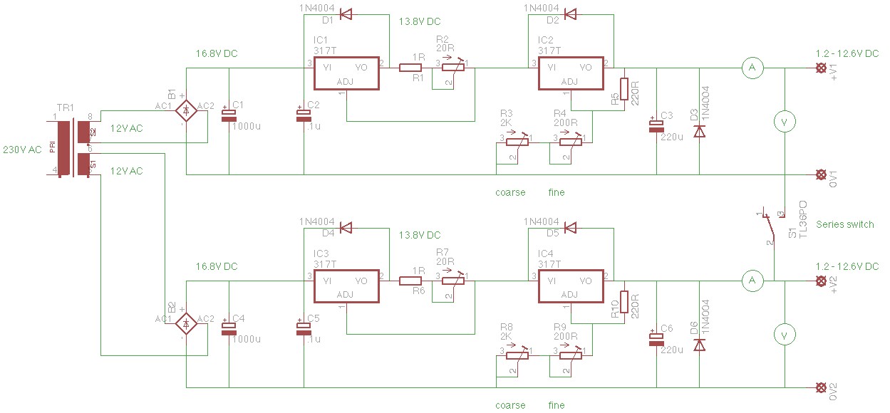
Please correct me if I'm wrong, but I think the circuit will work like this:
- 230V transformed to 12V AV then rectified should give 16.8V DC
- The first LM317 is set to constant current, so with R1 and R2, I will get a fixed current (current limit) between 60mA and 1.2A depending on where R2 is set
- There will be about 3v dropped across the LM317, so we now have about 13.8v
- The next LM317 is for voltage regulation. R3 and R4 are used as coarse and fine adjustment and should enable me to adjust from 1.2 - 12.6 volts DC
- As the circuit is duplicated off another secondary winding, the switch is used to make a dual series PSU enabling me to have -1.2v / 0v / +1.2v up to -12.6v / 0v / +12.6v DC
- Heat dissipation...With a maximum current of 1.2A and output voltage at 1.2V, I calculate the heat that needs to be disapated in the first LM317 is 3.6W (3v x 1.2A) and 15.12W (12.6v x 1.2A), total aprox. 19 Watts
Are my calculations correct, and if so, would this work? I have a 50VA dual 12v transformer kicking around and most of the bits to make this PSU, so it shouldn't cost me too much to build. I will also use a 5v regulator on each secondary winding also to power the digital volt meters and ammeters that I linked too from eBay earlier in the thread.
Just realised, I need a lot more capacitance after the bridge rectifier!
1) Adjustable voltage from 0 - 12 (1.5 - 12 would be fine)
2) Current limiting capabilities, max current around 1A
3) 2 supplies that can be switched to make a series PSU for -v / 0 / +ve
Here is my latest idea:
Please correct me if I'm wrong, but I think the circuit will work like this:
- 230V transformed to 12V AV then rectified should give 16.8V DC
- The first LM317 is set to constant current, so with R1 and R2, I will get a fixed current (current limit) between 60mA and 1.2A depending on where R2 is set
- There will be about 3v dropped across the LM317, so we now have about 13.8v
- The next LM317 is for voltage regulation. R3 and R4 are used as coarse and fine adjustment and should enable me to adjust from 1.2 - 12.6 volts DC
- As the circuit is duplicated off another secondary winding, the switch is used to make a dual series PSU enabling me to have -1.2v / 0v / +1.2v up to -12.6v / 0v / +12.6v DC
- Heat dissipation...With a maximum current of 1.2A and output voltage at 1.2V, I calculate the heat that needs to be disapated in the first LM317 is 3.6W (3v x 1.2A) and 15.12W (12.6v x 1.2A), total aprox. 19 Watts
Are my calculations correct, and if so, would this work? I have a 50VA dual 12v transformer kicking around and most of the bits to make this PSU, so it shouldn't cost me too much to build. I will also use a 5v regulator on each secondary winding also to power the digital volt meters and ammeters that I linked too from eBay earlier in the thread.
Just realised, I need a lot more capacitance after the bridge rectifier!
Last edited:
You need a bit bigger transformer. 16.8 - 12.6 = 4.2. That isn't near enough to drop across two regulators, but closer to what I would design for just one. Use a small fan on the heatsink if need be to keep things cool.
A 10μF capacitor from the 220Ω resistors to ground will improve ripple rejection appreciably. Insert a reverse-biased diode in parallel with each 220Ω.
The circuit only needs one diode across both regulators. Their function is to provide a current path around the regulators in case the input voltage falls before the output voltage.
I would use a separate small transformer to supply the digital stuff.
Last edited:
Cheers SofaSpud.
Are these the improvements you meant:
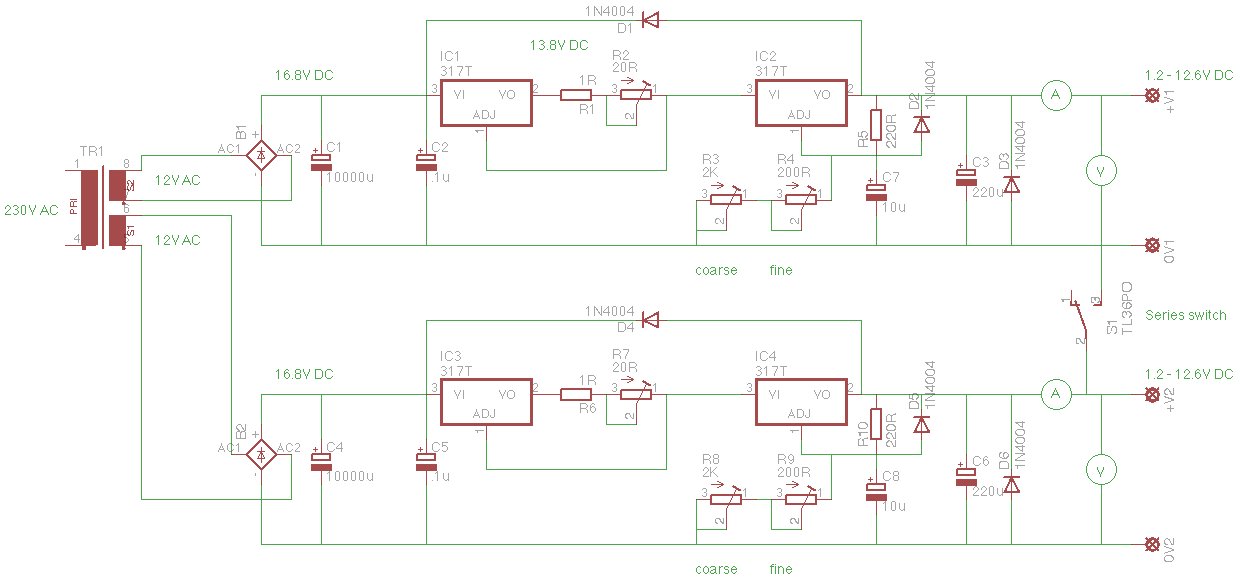
In theory, would this PSU give me what I want? apart from the voltage output I require! What would you expect the volatge out to be with this schematic. From the datasheet it looks like the LM317 only drops 1.2v when in voltage regulation mode and in constant current mode most people say it drops 3v, that's where I got 4.2v total.
Are these the improvements you meant:
In theory, would this PSU give me what I want? apart from the voltage output I require! What would you expect the volatge out to be with this schematic. From the datasheet it looks like the LM317 only drops 1.2v when in voltage regulation mode and in constant current mode most people say it drops 3v, that's where I got 4.2v total.
Last edited:
1.2V dropout? I'm not sure where you see that in the datasheet. Anyway, the actual formula for the standard regulators is Vdropout = 2(Vbe) + PNPsat which amounts to a minimum of 2-3 volts. The circuit will lose regulation if that gets too low, and for a reliable bench supply you want plenty of room to spare.
And yes, those are the additions from my other post. I don't think you need 10000μF at the filter caps. 4700μF or a couple 2200μF would be what I'd probably use.
And yes, those are the additions from my other post. I don't think you need 10000μF at the filter caps. 4700μF or a couple 2200μF would be what I'd probably use.
Last edited:
Thanks again. So a 2 x 15V transformer would be a better option for what I want then, as this would give me 21v DC to play with. So my total heat dissipation would be (if running max current of 1.2A and max voltage drop of 19.8V) about 23W per PSU.
If I don't want each heatsink to rise more that 30 deg C above an ambient temp of 25C would the heatsink I required be 30/23 = 1.3C/W? Obviously a smaller one if fan cooled.
I may have to change the resistors and pots on the voltage regulation LM317 as the value of the variable ones are hard to find.
Yes, and the heatsink calcs look good. These regs also like a minimum curent, so what you could do is reduce the 220Ω resistors to 120Ω which will set the minimum current at ~10mA. You could then reduce the potentiometers by half (1k & 100), which should be easier to find.
I've just found a transformer I have which is 230v supply and 0-25 0-25 output (300VA).
I think this would work for my benchtop PSU, but I think there might be a lot of heat to dissipate. 25V AC would give me 35V DC after the rectifier. If I set my PSU to 3v and drew a current of 1.5A, I would have to dissipate 48W of heat! Is this kind of heat dissipation normal for a PSU? With a 30degC rise above an ambient temp of 25degC I would need a 30/48 = 0.625C/W. I have few heatsinks I removed from some variable speed inverter drives which would work. I suppose the extra voltage available at the output of the PSU would be a good thing too, as I should be able to have a variable voltage from 1.2 up to 25+ volts.
I think this would work for my benchtop PSU, but I think there might be a lot of heat to dissipate. 25V AC would give me 35V DC after the rectifier. If I set my PSU to 3v and drew a current of 1.5A, I would have to dissipate 48W of heat! Is this kind of heat dissipation normal for a PSU? With a 30degC rise above an ambient temp of 25degC I would need a 30/48 = 0.625C/W. I have few heatsinks I removed from some variable speed inverter drives which would work. I suppose the extra voltage available at the output of the PSU would be a good thing too, as I should be able to have a variable voltage from 1.2 up to 25+ volts.
")
- Status
- This old topic is closed. If you want to reopen this topic, contact a moderator using the "Report Post" button.
- Home
- Amplifiers
- Power Supplies
- DIY Benchtop PSU, what about these.....