Hi all-
A Dynaudio active monitor is blowing fuses. Opened it up, disconnected the transformer output, fuse still blowing. Took out the transformer, reading a short on the primaries. Apparently this is a common issue on these, which is shameful, although I did pick the entire unit up for just $50.
Anyway, Dynaudio are a major buzz-kill in that they will not release ANY information. The supplier of the transformer is being equally vague, saying that it is a 50 VA part, 220~240 VAC primaries (not completely clear on how this works in the US, maybe jumper wires the primaries in parallel?), the secondaries are anywhere from 6 to 60 V, based on the code of the part A through Z, and this one is H.
So my problem is that the part is shorted, I can not think of a way to test the secondary voltage to see what replacement part to get. Do I open it up and count the turns?? Please help!
If the tranny is blowing the fuse with secondaries disconnected then as you say... its duff.
(Be aware though that primaries do read very low DC resistance on a DVM and on a big tranny it can be surprisingly low... that's normal... at AC the impedance is much higher)
Identifying voltages can be difficult and more so if there are multiple secondary windings. A good clue can be to look at the circuit and try and work back (if thats possible). For example a winding feeding a bridge and 25 volt reservoir cap automatically puts an upper limit on things at around 17 volts AC. It may be lower, but no higher. Then you have to look at what it feeds and so on. If it fed a 12 volt reg then you would need at least 15 volts DC so that give a lower limit of around 11 volts AC. Very rough and ready but you get the idea")
(Be aware though that primaries do read very low DC resistance on a DVM and on a big tranny it can be surprisingly low... that's normal... at AC the impedance is much higher)
Identifying voltages can be difficult and more so if there are multiple secondary windings. A good clue can be to look at the circuit and try and work back (if thats possible). For example a winding feeding a bridge and 25 volt reservoir cap automatically puts an upper limit on things at around 17 volts AC. It may be lower, but no higher. Then you have to look at what it feeds and so on. If it fed a 12 volt reg then you would need at least 15 volts DC so that give a lower limit of around 11 volts AC. Very rough and ready but you get the idea
If the tranny is blowing the fuse with secondaries disconnected then as you say... its duff.
(Be aware though that primaries do read very low DC resistance on a DVM and on a big tranny it can be surprisingly low... that's normal... at AC the impedance is much higher)
Identifying voltages can be difficult and more so if there are multiple secondary windings. A good clue can be to look at the circuit and try and work back (if thats possible). For example a winding feeding a bridge and 25 volt reservoir cap automatically puts an upper limit on things at around 17 volts AC. It may be lower, but no higher. Then you have to look at what it feeds and so on. If it fed a 12 volt reg then you would need at least 15 volts DC so that give a lower limit of around 11 volts AC. Very rough and ready but you get the idea
Thanks for confirming, this is my first diagnosis, and I am surprised that I even got this far! I will look at and around the bridge to ID the parts. It sounds like I will have to unbolt the assembly after all to get to the chip amps. Identifying what chip amps are being used will hopefully help. Thanks.
After the bridge, the seconderies go to a bank of caps rated at 35 V, then to a pair of LM3886. I suppose I need to go with whatever works best for these amps, and hope its compatible with the built in active crossover and filters. Any suggestions would be greatly appreciated!
BTW it looks to have 3 sets of primaries in a config I have not seen before:
(Lead 1, 2 or 3 selectable via jumper)
Lead 1 + Lead 4 = 230 V
Lead 2 + Lead 4 = 120 V
Lead 3 + Lead 4 = 100 V
I wander if this design is what is responsible for the high rate of failure in these transformers..
Thanks!
BTW it looks to have 3 sets of primaries in a config I have not seen before:
(Lead 1, 2 or 3 selectable via jumper)
Lead 1 + Lead 4 = 230 V
Lead 2 + Lead 4 = 120 V
Lead 3 + Lead 4 = 100 V
I wander if this design is what is responsible for the high rate of failure in these transformers..
Thanks!
Multiple primary options are pretty common and shouldn't be a source of trouble.
It might help to see pictures of the tranny and the PCB. For example, is it running on a single "up to 35 volt rail"or a dual rail of "up to -/+35 volts). Also are there any other rails derived from other windings ?
It might help to see pictures of the tranny and the PCB. For example, is it running on a single "up to 35 volt rail"or a dual rail of "up to -/+35 volts). Also are there any other rails derived from other windings ?
Here are some pics of the situation. My best guess is that there are 2 identical rails total.
My only concern about the primaries configuration is that it indeed invalidates my test with a meter, since all leads are actually connected, and a reading of continuity is to be expected..
My only concern about the primaries configuration is that it indeed invalidates my test with a meter, since all leads are actually connected, and a reading of continuity is to be expected..
Attachments
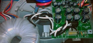
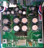
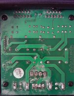
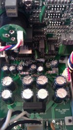
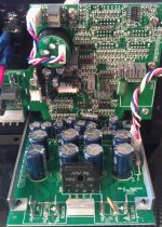
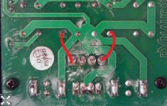
It certainly looks that way. Can you confirm there is continuity here. Bit hard to be 100% sure looking at the pics. I think those eight caps are just paralled up in pairs. They must be I can see the outer caps link to the bridge and ground via top and bottom traces.
So each of those caps is 35 volts... yes ?
That means that 35/1.414 gives the theoretical max AC voltage per winding which would be 24 volts AC. That's to close for comfort with no safety margin. 18 volt is a common off the shelf value and would give -/+25 volts DC under load, higher than that off load, higher by the regulation factor of the tranny which could be 4 to 7% or so. Perhaps 27 to 28 volts DC.
So thats a real possibility, an 18-0-18
22 vac trannys are available but less common. That works out at -/+33 volts DC (ish) off load for a typical tranny. That's a bit near the limits of the caps.
Lets look at power output. 25-0-25 vdc would allow around a (guess) -/+21 or 22 volt swing into 8 ohms. Thats 21/1.414 which is around 15 volts RMS. Into 8 ohms thats 28 watts RMS. Does that fit in with any published specs ?
Next step is to determine the VA rating. If you measure the tranny dimensions you can compare with others,
Your Search Results | CPC | Results
look at the unencapsulated ones lower down the page.
I can see the outer caps link to the bridge and ground via top and bottom traces.So each of those caps is 35 volts... yes ?
That means that 35/1.414 gives the theoretical max AC voltage per winding which would be 24 volts AC. That's to close for comfort with no safety margin. 18 volt is a common off the shelf value and would give -/+25 volts DC under load, higher than that off load, higher by the regulation factor of the tranny which could be 4 to 7% or so. Perhaps 27 to 28 volts DC.
So thats a real possibility, an 18-0-18
22 vac trannys are available but less common. That works out at -/+33 volts DC (ish) off load for a typical tranny. That's a bit near the limits of the caps.
Lets look at power output. 25-0-25 vdc would allow around a (guess) -/+21 or 22 volt swing into 8 ohms. Thats 21/1.414 which is around 15 volts RMS. Into 8 ohms thats 28 watts RMS. Does that fit in with any published specs ?
Next step is to determine the VA rating. If you measure the tranny dimensions you can compare with others,
Your Search Results | CPC | Results
look at the unencapsulated ones lower down the page.
Attachments
Yes the caps are 35 V, and from the transformer part number I know it is 50 VA, and 13% regulation factor, just don't know the secondaries voltage. I have been able to acquire a second, working monitor, so I am thinking to just open it up and poke around with a volt meter..
And yes, I can confirm that there is continuity between all 4 primary/input leads of the transformer, which makes sense after looking at the jumper trace leads (the jumper selects between 230 V, 120 V and 100 V), I think it just taps into the same primary winding only at different places, of course this is me guessing.
And yes, I can confirm that there is continuity between all 4 primary/input leads of the transformer, which makes sense after looking at the jumper trace leads (the jumper selects between 230 V, 120 V and 100 V), I think it just taps into the same primary winding only at different places, of course this is me guessing.
Last edited:
The 50 va rating sounds small tbh but of course that depends on the units intended output. And your 13% regulation fits in with a small tranny. Small trannys have poor regulation compared to large.
I think the 18-0-18 is a real possibility here. The link I gave you shows a 50va one at 76 by 30 mm. How does that compare in size to the original ?
Worry about primary connections when you have decided what to fit. If you have another identical unit then of course have a measure and see what the voltages really are

Hmmm... you can't get that output from a 50 va tranny.
OK, here's an 85 by 41mm that is 100va. The figures 50va and two times 50 watts RMS just don't add up. Voltage wise it could reach the required swing for 50 watts RMS into 4 ohms on an 18 volt tranny.
MCTA100/18 - MULTICOMP - 100VA TOROIDAL 2X18V | CPC
I'm pretty much out of time for tonight
(One thing you can check. Is that 50 watts RMS quoted as being into 4 or 8 ohms... or any other figure)
A 50W amplifier will run satisfactorily from a 50VA to 100VA transformer.
Music systems that run at output powers well below maximum can take advantage of the amplifier's ability to work with a very wide range of transformer sizes.
This applies very much so with all domestic listening equipment, where average output power is usually well below 1/10th of the maximum and often less then 1/100th of the maximum output.
This would lead to "adequate" music reproduction from a pair of 50W amplifiers running from one 50VA transformer.
But turn the volume up such that the average power drawn from the amplifier is more than 1/10th of the maximum capability and the transformer will begin to heat up. There's the problem.
A 50W amplifier will run satisfactorily from a 50VA to 100VA transformer.
Music systems that run at output powers well below maximum can take advantage of the amplifier's ability to work with a very wide range of transformer sizes.
This applies very much so with all domestic listening equipment, where average output power is usually well below 1/10th of the maximum and often less then 1/100th of the maximum output.
This would lead to "adequate" music reproduction from a pair of 50W amplifiers running from one 50VA transformer.
But turn the volume up such that the average power drawn from the amplifier is more than 1/10th of the maximum capability and the transformer will begin to heat up. There's the problem.
This makes me wander if I should go with more than 50 VA on both units, upgrade the working one as well, since I will have both open and ordering parts anyway. On the other hand, each of the LM3886's are directly connected to either the tweeter or the mid-bass, with an active XO before the amp, so perhaps going beyond the 50 VA is overkill for this application?
I suppose ultimately I am constrained by the size of the bracket to which the transformer is bolted, the design of the entire unit is somewhat compact..
By the way, Dynaudio offered to send me a replacement part for about $100 plus shipping, and will take only 3 weeks or so, and if I am lucky, it will last as long as a normal transformer. I love the sound of their drivers, but this high rate of transformer failures smacks of design compromise.
As you have have access to a working unit then you really should measure the AC voltage from the tranny as 100% confirmation.
We've made a best guesstimate... and there's no problems with the figures we've used, but it would be nice to know for sure, particularly as you actually have a working one. For example, did they really push to the absolute limits and use a less common 22-0-22 tranny.
We've made a best guesstimate... and there's no problems with the figures we've used, but it would be nice to know for sure, particularly as you actually have a working one. For example, did they really push to the absolute limits and use a less common 22-0-22 tranny.
Yes, open op the other unit and do a measurement of the AC voltage.
Best is actually to disconnect the transformer on the secondary side, to get the non loaded voltage rating.
If you end up with needing a voltage which is not available, you can use one with a little less voltage rating, and make a few turns yourself, connecting these ins series with the secondaries to get the desired voltage (that is of course if it's a toroid)
What Dynaudio monitor are we talking about??
Best is actually to disconnect the transformer on the secondary side, to get the non loaded voltage rating.
If you end up with needing a voltage which is not available, you can use one with a little less voltage rating, and make a few turns yourself, connecting these ins series with the secondaries to get the desired voltage (that is of course if it's a toroid
)What Dynaudio monitor are we talking about??
What Dynaudio monitor are we talking about??
It is BM5A mkII. I have been using B&W 604 with a large discreet amp, and the Dynaudio's sound a lot better to me. My room might have something to do with it, but I have taken then B&W's apart, and the tweeters used there are just a joke.
That sounds like an 18 volt tranny. Offload and the voltage rises by the "regulation factor" of the particular transformer. The one in my link was 8% so that would give around 20 volts off load. And that was a 100va tranny. Smaller one have worse (higher percentage) regulation.
Its an 18-0-18
Its an 18-0-18
Hmmm... you can't get that output from a 50 va tranny.
OK, here's an 85 by 41mm that is 100va. The figures 50va and two times 50 watts RMS just don't add up. Voltage wise it could reach the required swing for 50 watts RMS into 4 ohms on an 18 volt tranny.
Of course the stated specs were wrong, after measuring it my self, it is actually 85 x 25 mm, so that sounds about right.
- Status
- This old topic is closed. If you want to reopen this topic, contact a moderator using the "Report Post" button.
- Home
- Amplifiers
- Power Supplies
- Transformer specs for Dynaudio monitor