Hi,
I need some help figuring this out and YES I am a noob
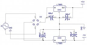
The problem is that the voltage I am seeing after the 7905 is about -8.5V when it clearly should be -5V
I have tried several 7905's with the same results.
I do get +5V from the 7805.
and I get -12V and +12V directly after the rectifier
I have used the same 7805 and 7905 with a ATX power supply with +/-12V and that works great.
I have attached the schematic.
Any ideas would be great.
Thanks.
I need some help figuring this out and YES I am a noob
The problem is that the voltage I am seeing after the 7905 is about -8.5V when it clearly should be -5V
I have tried several 7905's with the same results.
I do get +5V from the 7805.
and I get -12V and +12V directly after the rectifier
I have used the same 7805 and 7905 with a ATX power supply with +/-12V and that works great.
I have attached the schematic.
Any ideas would be great.
Thanks.
Attachments
Hi,
I need some help figuring this out and YES I am a noob
The problem is that the voltage I am seeing after the 7905 is about -8.5V when it clearly should be -5V
I have tried several 7905's with the same results.
I do get +5V from the 7805.
and I get -12V and +12V directly after the rectifier
I have used the same 7805 and 7905 with a ATX power supply with +/-12V and that works great.
I have attached the schematic.
Any ideas would be great.
Thanks.
IIRC 7805 and 7905 have different pinouts. Did you verify?
jan
hyperion007, AndrewT gave You the answer. Read datasheet.minimum current stated in datasheet?
minimum current stated in datasheet?
another unhelpful post?
Not at all... I've come across "minimum currents" on regulators before.
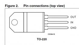
I am using TO-220
What is that about the case being Vin? See attachment.
And no, the 7905 is in a breadboard and no other component is touching the case.
Vin is on the case of the 7905
See datasheet. www.jaycar.com.au/images_uploaded/LM7905.PDF
Pinout is Common (Gnd), In, Out, looking from the front. Carefully check your wiring, particularly gnd of 7905 as it appears like a component not in your diagram but on the board is lifting it higher. Your diagram shows 2 ground wires ?, perhaps you are providing paths for 7805 and 7905 yet they are joined on your diagram at the regulator pins. Can you see why two wires are unnecessary if already joined at regulators. Two wires to a common point is nice but circumvented if the regulators already share gnd.
The answer is simple, but i don't want to blame anyone.Hi,
I need some help figuring this out and YES I am a noob
The problem is that the voltage I am seeing after the 7905 is about -8.5V when it clearly should be -5V
I have tried several 7905's with the same results.
I do get +5V from the 7805.
and I get -12V and +12V directly after the rectifier
I have used the same 7805 and 7905 with a ATX power supply with +/-12V and that works great.
I have attached the schematic.
Any ideas would be great.
Thanks.
If you can exclude any error in layout and wirig the IC is oscillating.
Check with a sope and try it with a resistive load and different cap
or caps on output.
For heavy loading the input caps are too small.
but how come it works when using the ATX power supply? I have also read that the 7805 and 7905 do not need minimum current draw
I don't know what this ATX is. So far you only describe your 7805, 7905 setup.
Please note that I don't talk about minimum current, but without load it may oscillate.
Your DVM can not read this. Again, did you check with your scope?
Please consider that you probably used a 7909 which in my eyes (without my
glasses) looks very similar to 7905 .
but how come it works when using the ATX power supply? I have also read that the 7805 and 7905 do not need minimum current draw
So then ask yourself: what exactly is the difference between the two situations?
Is there a difference in input/output caps? Difference in input voltage? Think!
The reg needs a cap both at the input and the output to be stable, close to the pins. Even 10uF is enough for stability.
You may also try to load it a bit to see if that makes a difference. Asking here is good, doing some research is better
jan
I have tried to figure it out myself but didn't want to burn anything up so I thought I would ask.
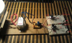
I have tried connecting a 4.7K resistor and a LED between negative output from 7905 and GND to put some load on the 7905 but the only thing that happened was the voltage dropped from about -8V to -7.12V
I have attached a picture of the test setup.
I don't think I can put the caps any closer to the 7805/7905
Attachments
- Status
- This old topic is closed. If you want to reopen this topic, contact a moderator using the "Report Post" button.
- Home
- Amplifiers
- Power Supplies
- wrong voltage 7905?