I am building a power supply to provide 30VDC at 2A. The filter capacitor is 20,000µF following a full-wave bridge. I am trying to determine if the filter capacitor can withstand the ripple current. I have calculated the ripple voltage using Vripple = I/2fC; where, I is the current drawn in amps, f is the line frequency in Hertz, and C is the capacitance in Farads. Thus:
Vripple = 2/2*60*.02 = .83. This voltage is peak-to-peak.
To approximate Vrms, I used Vrms = Vpp/2*sqrt(2). Thus: Vrms = .83/2*sqrt(2) = .29.
Here’s my question: Is calculating the ripple current as simple as Ohm’s Law? That is, is the ripple current equal to Vrms/Z ? The capacitor, actually two Panasonic TS-UP 10,000µF capacitors in parallel, each have an ESR of .04Ω at 120Hz. I assume the effective ESR is halved by using the capacitors in parallel. If so, the ESR is about .02Ω. I calculated Z using Z = sqrt ((1/2πfC)^2 + ESR^2). Thus: sqrt((1/2π*120*.02)^2 + (.02)^2) = .069. Using Ohm’s Law, the ripple current is .29/.069 or 4.2A.
I’m not asking for someone to check my math; rather, is my approach correct?
Many thanks,
George
It doesn't seem to be too far off. I'd use this approach:
The RMS current in the transformer winding is the same as the RMS current on the DC side of the rectifier before the filter capacitor. That current is the output current plus the capacitor current. Also, the capacitor current has no DC component and the output current has no AC component. Because of this, (transformer RMS current)^2 = (dc output current)^2 + (capacitor RMS current)^2.
For typical values of transformer impedance at this power level and a large capacitor (ripple lower than 40% or so) you end up with the rule-of-thumb value of transformer RMS current = 1.8 * dc output current. For this case, by inserting this into the previous equation, the capacitor RMS current becomes sqrt(1.8^2-1^2) * dc output current = 1.5 * dc output current.
So you end up with about 3 A (RMS) capacitor ripple current and 3.6 A (RMS) transformer secondary current. Also, be careful about output voltage which is going to be lower than sqrt(2) * nominal transformer RMS voltage even considering diode voltage drop. It ends up being about 90%-95% of that because of the distorted current waveform causing voltage drop in the transformer. I like to simulate these kind of circuits but you need a good estimate of transformer impedance (winding resistance and leakage inductance) to get meaningful results at all.
But anyways, 3 A or 4.2 A ripple current should not be a problem for a typical 20 mF capacitor/capacitor bank.
Last edited:
For an approximate answer the approach may work. There are two weaknesses:
1. the conversion from Vripple to Vrms assumes a sinewave, when in fact it is a rough approximation to a sawtooth.
2. the calculation of RMS ripple current from Vrms assumes that ESR dominates over capacitive reactance.
You could check your model using PSUD2.
1. the conversion from Vripple to Vrms assumes a sinewave, when in fact it is a rough approximation to a sawtooth.
2. the calculation of RMS ripple current from Vrms assumes that ESR dominates over capacitive reactance.
You could check your model using PSUD2.
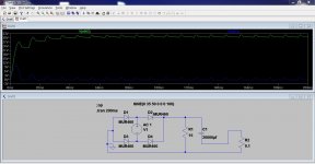
Hardly a shining example of (my ") ) simulation skills but the peak currents are as expected very high. This is the voltage across the 0.1 ohm which I guessed was comparable to resistive and ESR losses is a real circuit. Top trace is the voltage across the cap i.e. the supply.
) simulation skills but the peak currents are as expected very high. This is the voltage across the 0.1 ohm which I guessed was comparable to resistive and ESR losses is a real circuit. Top trace is the voltage across the cap i.e. the supply.
) simulation skills but the peak currents are as expected very high. This is the voltage across the 0.1 ohm which I guessed was comparable to resistive and ESR losses is a real circuit. Top trace is the voltage across the cap i.e. the supply.Attachments
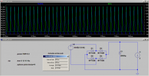
Quick sim in LTSpice shows an rms ripple current of 4.75A however this was simmed with NO series resistance on the voltage source, so in the real world I imagine it should be lower due to resistance in the secondary of the transformer.
Putting a series resistance of 0.1 ohms in the voltage source dropped the current to 4A. I'm not sure what a reasonable figure would be to add in (as the series resistance) to make it more realistic.
edit: haha mooly, we both had similar ideas I was a bit slower!
Tony.
Putting a series resistance of 0.1 ohms in the voltage source dropped the current to 4A. I'm not sure what a reasonable figure would be to add in (as the series resistance) to make it more realistic.
edit: haha mooly, we both had similar ideas I was a bit slower!
Tony.
Attachments
Last edited:
Try 27.5V RMS in series with 0.63 ohms for something resembling a 100VA 25V transformer with 10% regulation. (10% * 25V / (100VA / 25V) = 0.63 ohms) Such a configuration should give close to 30V at full load and nominal line if I remember correctly.
A transformer with tighter regulation can be rated at a lower nominal voltage for the same output voltage. Though, if 30V is desired voltage after a linear regulator, something close to a 30V transformer will probably be needed considering low line, ripple and dropout.
edit: Regarding an earlier simulation in the thread, 20 mF of capacitors will hopefully have a much lower ESR than 0.1 ohms... Probably more like on the order of 0.01 ohms.
Last edited:
edit: haha mooly, we both had similar ideas I was a bit slower!
Tony.
You managed to get some data figures into yours... I'd have to reach for the text books to remind me how to do that
I am building a power supply to provide 30VDC at 2A. The filter capacitor is 20,000µF following a full-wave bridge. I am trying to determine if the filter capacitor can withstand the ripple current. I have calculated the ripple voltage using Vripple = I/2fC; where, I is the current drawn in amps, f is the line frequency in Hertz, and C is the capacitance in Farads. Thus:
Vripple = 2/2*60*.02 = .83. This voltage is peak-to-peak.
To approximate Vrms, I used Vrms = Vpp/2*sqrt(2). Thus: Vrms = .83/2*sqrt(2) = .29.
Here’s my question: Is calculating the ripple current as simple as Ohm’s Law? That is, is the ripple current equal to Vrms/Z ? The capacitor, actually two Panasonic TS-UP 10,000µF capacitors in parallel, each have an ESR of .04Ω at 120Hz. I assume the effective ESR is halved by using the capacitors in parallel. If so, the ESR is about .02Ω. I calculated Z using Z = sqrt ((1/2πfC)^2 + ESR^2). Thus: sqrt((1/2π*120*.02)^2 + (.02)^2) = .069. Using Ohm’s Law, the ripple current is .29/.069 or 4.2A.
I’m not asking for someone to check my math; rather, is my approach correct?
Many thanks,
George
It doesn't seem to be too far off. I'd use this approach:
The RMS current in the transformer winding is the same as the RMS current on the DC side of the rectifier before the filter capacitor. That current is the output current plus the capacitor current. Also, the capacitor current has no DC component and the output current has no AC component. Because of this, (transformer RMS current)^2 = (dc output current)^2 + (capacitor RMS current)^2.
For typical values of transformer impedance at this power level and a large capacitor (ripple lower than 40% or so) you end up with the rule-of-thumb value of transformer RMS current = 1.8 * dc output current. For this case, by inserting this into the previous equation, the capacitor RMS current becomes sqrt(1.8^2-1^2) * dc output current = 1.5 * dc output current.
So you end up with about 3 A (RMS) capacitor ripple current and 3.6 A (RMS) transformer secondary current. Also, be careful about output voltage which is going to be lower than sqrt(2) * nominal transformer RMS voltage even considering diode voltage drop. It ends up being about 90%-95% of that because of the distorted current waveform causing voltage drop in the transformer. I like to simulate these kind of circuits but you need a good estimate of transformer impedance (winding resistance and leakage inductance) to get meaningful results at all.
But anyways, 3 A or 4.2 A ripple current should not be a problem for a typical 20 mF capacitor/capacitor bank.
The downloadable spreadsheet at the following link should do what you need. It doesn't use any approximations because it solves the differential equations numerically.
http://www.diyaudio.com/forums/power-supplies/216409-power-supply-resevoir-size-167.html#post3287619
It also has spice model parameters for a transformer. Additionally, the transformer model was per-unitized so it can be scaled, such that you can enter a different Volt-Amps rating, or a different output or input voltage, or a different line frequency, and the spreadsheet will calculate a new set of spice model parameters for you.
There is also a section with the measurements on which the model is based, with instructions for measuring a different transformer.
Earlier in that thread, many more spice-simulation specifics are given, along with downloadable .asc files for LT-Spice.
cool Tom I have downloaded and will check it out, I'll have to track down the LTSpice transformer model too!
Megajocke the 0.1 ohms was a paracitic on the voltage source. The cap (which I scaled up from a different model I had lying around) had ESR set at 0.05 which is definitely too high.
Tony.
Megajocke the 0.1 ohms was a paracitic on the voltage source. The cap (which I scaled up from a different model I had lying around) had ESR set at 0.05 which is definitely too high.
Tony.
Megajocke the 0.1 ohms was a paracitic on the voltage source. The cap (which I scaled up from a different model I had lying around) had ESR set at 0.05 which is definitely too high.
I was referring to Mooly's simulation back there. 0.1 ohms voltage source series resistance would be quite a large transformer.
Osvaldo de Banfield: The OP stated 30VDC at 2A, but what you said sure is correct if the load current has an AC component. (unless it is of low frequency compared to the line frequency)
gootee: Thanks for the link. I think I saw that thread some while ago.
- Status
- This old topic is closed. If you want to reopen this topic, contact a moderator using the "Report Post" button.
- Home
- Amplifiers
- Power Supplies
- Help with Ripple Current