Gents,
I am building a 6AS7 based headphones amp with an LM338k regulated power supply. When I power it up, the heater voltage sags to just 1.2volts. I have checked everything and the unloaded supply reads well at 6.31 volts. But load with even one tube, and the supply simply sags to 1.2 volts. Does anyone have any idea what I could be looking at?
Cheers
I've been told to account for at least three times current at cold start, which takes you well over the 5Amps allowed by an LM338.
But it's quite likely to be input voltage dropping, as mentioned above.
You could try setting the regulator to say 8.8V and putting a 1 ohm resistor in series. This means your total resistance will be higher and your current lower over the warm up period. You'll need at least a 7W resistor suitably heat sunk. But then I don't know your reg's input voltage.
You could also try increasing the heat sink on the reg. As maybe it can cope with the brief over current when suitably cooled.
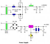
Thanks for the reply thus. Here's the circuit which I built. The transformer was specified at 50 VA. What I found last night is that this happens even when I just have the driver tube (6922) plugged in. I've got the power regulator on a generous heat sink and it does get quite warm.
Because I power up through a variac, would the ramping up cause a voltage violation issue with the LM 338K?
Cheers
Because I power up through a variac, would the ramping up cause a voltage violation issue with the LM 338K?
Cheers
Attachments
A slow ramp up might mean that the regulator is still struggling with insufficient voltage drop when it hits the current or temperature limit too. Better heatsinking might help, or add a resistor a Robert suggested.
A 50VA transformer will be able to continuously supply about 15-20W DC, so maybe 1.5A.
A 50VA transformer will be able to continuously supply about 15-20W DC, so maybe 1.5A.
A 50VA transformer will be able to continuously supply about 15-20W DC
Where are those numbers from? Sounds interesting...
I have about 9.3 volts AC on the transformer primary. What concerns me is that even the 6922 by it self does not start. I had the wires twisted although I am using DC heaters. Would this be adding excessive capacitance to the power supply load?
I started just the 6922 heaters without any ramp up but it still refused to go higher then 1.24 or so volts.
Cheers!
I started just the 6922 heaters without any ramp up but it still refused to go higher then 1.24 or so volts.
Cheers!
Would this be adding excessive capacitance to the power supply load?
No. Think of big caps with several dozens of 1000uF which are no problem. Twisted wires add a couple of picofarads...
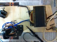
how big (physically) is your transformer?
I have about 9.3 volts AC on the transformer primary.
Secondary, right?
(...) but it still refused to go higher then 1.24 or so volts.
Sounds like two diode drops. Did you use 4 diodes for the rectifier or a singe bridge?
To get a clearer picture can you please:
Give all component values,
Measure DC and AC voltages on all regulator pins,
Measure the current from reg-out to heater wiring when volts are low,
Test the circuit with a dummy load 22 Ohms 5W or a dial lamp 7V 0.3A. The 6922 is rated at 0.3A.
Test the heater wiring with a bench supply, a 6V battery, 5V wall wart, or a simple heater transformer. Use a fuse!
Just a thought: 1.24V is the typical Vreg of the LM338.
I can't remember, but you should be able to find them in books on power supplies. The basic idea is that the charging pulses for an electrolytic reservoir cap have a much higher RMS/average ratio than the resistive load assumed by transformer VA ratings. You have to derate by some factor around 2 or 3 (I can't remember the actual figure).Preamp said:Where are those numbers from? Sounds interesting...
If the DC is powering a Class B/AB power amp then you can get most of that factor back again because of the duty cycle of real music. Thus a 50VA transformer can (very roughly!) just about power a 50W amp (or 25W stereo). Heaters draw continuous current so you lose this advantage.
To get a clearer picture can you please:
Just a thought: 1.24V is the typical Vreg of the LM338.
Hi, I am using 1/4 watt resistors to set the reference voltage (2 x 180R). Would there be a concern with the size of these resistors? I can't seem to find anywhere in the data sheet where it specifies the rating for these resistors.
Cheers!
Hi,
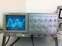
With load, the waveform to the bridge rectifier is about 9.5 volts p-p.
The voltage at the input of the power regulator is about 10.4 volts DC. The waveform pretty flat with some noise at the 1mV setting. This measurements were taken with just the 6922 plugged in. With a good 10volts supply entering the Lm338K, I am beginning to suspect the power regulator is not set up correctly. The circuit was built as per the following schematic.
The bottom section is of course the heater section that's causing grief.
Cheers!
Attachments
1.25^2/180 = a lot less than 250mWHi, I am using 1/4 watt resistors to set the reference voltage (2 x 180R). Would there be a concern with the size of these resistors? I can't seem to find anywhere in the data sheet where it specifies the rating for these resistors.
Cheers!

The other resistor can sometimes need a half watt or more, but not at 6.3V
I'm wondering if your heat sink/case of regulator, is shorting with something
It would not help, the drop out current is less than 1 amp with low voltage differential. I do not know the fold back characteristics of this device but it may have gone into some sort of foldback.Because I power up through a variac, would the ramping up cause a voltage violation issue with the LM 338K?
Cheers
Try applying full power to the circuit then switching on a heater load. The transient load from a cold heater can be determined by measuring the cold resistance, the valve datasheet may mention it as well.
There is a simple soft start circuit on the TI lm138 datasheet, this might be another option if the variac is causing trouble
Just check you have connected the 338K the right way
Gents,
After a good summer holiday, a fresh re-look into the circuit revealed what was wrong. Thee feedback resistors were built into a small PCB that was mounted onto the voltage setting terminal of the LM338K. A wire was to provide voltage from the output of the LM338K back to this circuit. However, due to a fault in connection, no voltage was flowing back from the output to the resistor/trimpot network. Re-did the connection and the circuit came up beautifully. Thanks every one for the input!
After a good summer holiday, a fresh re-look into the circuit revealed what was wrong. Thee feedback resistors were built into a small PCB that was mounted onto the voltage setting terminal of the LM338K. A wire was to provide voltage from the output of the LM338K back to this circuit. However, due to a fault in connection, no voltage was flowing back from the output to the resistor/trimpot network. Re-did the connection and the circuit came up beautifully. Thanks every one for the input!
- Status
- This old topic is closed. If you want to reopen this topic, contact a moderator using the "Report Post" button.
- Home
- Amplifiers
- Power Supplies
- Voltage sag on heater PSU