I think it really depends on the application and layout, just throwing low ESR caps at the reg with values chosen indiscriminately may risk oscillation, but it is far from a general rule. I have 4-5 builds where the LM317/337 are used very successfully with low ESR caps, with measurements to back it up. all have ceramic bypass + polymer caps and not a sniff of oscillation/resonance.
these are all projects by Owen (opc) and extensive measurements figure very highly in the development and all are taken with high dollar measurement gear (AP2 + more) and a skilled technician. care must be taken with layout, but these are all well executed SMD multilayer boards.
results of the projects they power are some of the best results ive seen here on the forum, several of them test the abilities of the AP2 analogue input/ADC
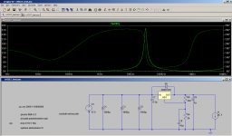
Hi qusp, it won't necessarily cause oscillation, but it may cause nastyness in the output impedance of the reg. Attached is a sim of Hengy's circuit. I put an arbitrary esr of 0.1 ohms for the 1uF cap (probably a bit low for an electro, but quite likely high for a 1uF ceramic!).
The impedance peak is around 27 ohms at 30Khz!! It is only a sim, but unfortunately I don't have the knowledge (or probably the equipment) to do output impedance measurements on the real thing")
I had to go to around 100uF output cap and 0.7 ohms before I could get rid of all traces of the resonance...
edit: of course adding some series resistance via a small value resistor is another option and is what I did with my PS with low esr electros utilized.
Tony.
The impedance peak is around 27 ohms at 30Khz!! It is only a sim, but unfortunately I don't have the knowledge (or probably the equipment) to do output impedance measurements on the real thing
I had to go to around 100uF output cap and 0.7 ohms before I could get rid of all traces of the resonance...
edit: of course adding some series resistance via a small value resistor is another option and is what I did with my PS with low esr electros utilized.
Tony.
Attachments
Last edited:
I know what you mean, but like I said, as a blanket statement its incorrect, but like adding bypass caps to anything it needs care in application.
the builds of opcs were absolutely put through the ringer at RIM on AP2, APxwhere he works (measured in reality) and no aberrations of any kind. but he will have modeled the layout, modeled the circuit and then prototyped different values.
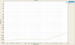
i'll see if I can dig up the independant measurements of the PSU on its own, but here is the SE-SE version of the headphone amp being powered by it.
the schematic includes ceramic bypass + 330µf polymer, then of course more ceramics and polymers of the same types in parallel to that at the load end
I think you'll agree, there is nothing of concern there....
and its the same on the LPUHP amp (see below), which is literally the cleanest 15-20W i've ever seen, which is packed with ceramic on the reg output (reference bypass) plus as there is 8 buffers in parallel per channel, it has 8 x 10uf ceramics in parallel per rail on the buffers and 3 x 1uf per rail on the instrumentation FE/VAS... all ceramics, so that would be pretty low ESR
same with his big poweramp which uses 317/337 for the lme49830 input. its all about the application
the builds of opcs were absolutely put through the ringer at RIM on AP2, APxwhere he works (measured in reality) and no aberrations of any kind. but he will have modeled the layout, modeled the circuit and then prototyped different values.
i'll see if I can dig up the independant measurements of the PSU on its own, but here is the SE-SE version of the headphone amp being powered by it.
the schematic includes ceramic bypass + 330µf polymer, then of course more ceramics and polymers of the same types in parallel to that at the load end
I think you'll agree, there is nothing of concern there....
and its the same on the LPUHP amp (see below), which is literally the cleanest 15-20W i've ever seen, which is packed with ceramic on the reg output (reference bypass) plus as there is 8 buffers in parallel per channel, it has 8 x 10uf ceramics in parallel per rail on the buffers and 3 x 1uf per rail on the instrumentation FE/VAS... all ceramics, so that would be pretty low ESR
same with his big poweramp which uses 317/337 for the lme49830 input. its all about the application
Attachments
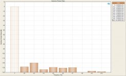
I particularly like the relative level measurements on the headphone amp =)
and this quote
and this quote
opc said:To put it into perspective, the highest harmonic here would produce about 3.12 femto-watts into a 32 ohm headphone.
Last edited:
SY, wintermute,
I have tried the circuit in in about 4 different places (10s of km away), and I always turn off and unplug as many things as possible. The first time I made the circuit, I noticed that my wireless keyboard would induce 50mVpp noise, and my cell phone would induce 200+mVpp noise when placed close!
The spikes you see in my pics are consistent between each location, so it would be logical to say that it is the smps that is making the noise, as it is common in every location.
I realize that I will have to shield my enclosure against EM and RF noise, as well as pay attention to the grounding when I finally put the circuit on perfboard.
I think that the noise that I am hearing in my headphones is caused by the smps, so I will try that first.
I might see if i can source a battery and take some measurements. That should give me a good idea of if it is in fact the smps or not creating the noise.
Thanks for your suggestions and ideas!
Hengy
The LM317 bandwidth is too low to do anything about the switching noise from the SMPS. Use 10uH on the input to the regulator. You can also deploy the circuit from Wenzel Associates "Finesse Voltage Regulator Noise" -- it works -- but adds a bit of complexity.
LM317's aren't fond of low ESR caps on the output -- use 100uF aluminum electrolytic. This isn't a low dropout regulator where the output cap is more critical, but a low ESR tantalum will cause an impedance peak and if the Q is high enough it will oscillate.
LM317's aren't fond of low ESR caps on the output -- use 100uF aluminum electrolytic. This isn't a low dropout regulator where the output cap is more critical, but a low ESR tantalum will cause an impedance peak and if the Q is high enough it will oscillate.
Hi qusp, not questioning the results of the connected equipment (and I am a complete novice compared to opc!!), but the effect is real It may not of course cause any problems with particular circuits.
I think that this paper http://www.calex.com/pdf/3power_impedance.pdf is a good one to talk about the effects.
What I found with my sims was that with the LM317, the bigger the output cap the lower the series resistance required to dampen the resonance. I ended up going with 1000uF and 0.3 ohms added series resistance. This resulted in the (simmed) lowest output impedance up to quite high frequencies (well outside the audio band).
As I understand it having a higher output impedance at certain frequencies will result in more modulation of the PS at those said frequencies. If the PSRR of the circuit being driven is good enough this will probably not matter. However I like to remove the possibility in the first place
Tony.
It may not of course cause any problems with particular circuits. I think that this paper http://www.calex.com/pdf/3power_impedance.pdf is a good one to talk about the effects.
What I found with my sims was that with the LM317, the bigger the output cap the lower the series resistance required to dampen the resonance. I ended up going with 1000uF and 0.3 ohms added series resistance. This resulted in the (simmed) lowest output impedance up to quite high frequencies (well outside the audio band).
As I understand it having a higher output impedance at certain frequencies will result in more modulation of the PS at those said frequencies. If the PSRR of the circuit being driven is good enough this will probably not matter. However I like to remove the possibility in the first place
Tony.
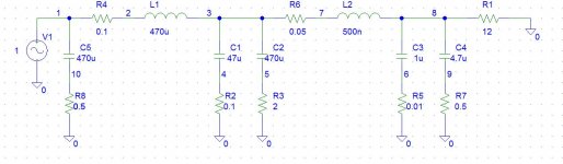
Simple RLC PS filter
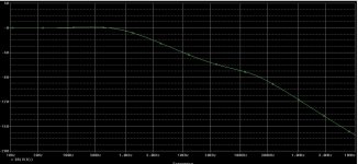
An RLC filter at the output of the power adapter can reduce the fundamental switching noise and its harmonics to a fairly low level. The attached PSpice schematic and simulation result show a two section RLC filter designed to attenuated switching noise above 50KHz.
L1, C1, L2, and C3 comprise the main filter components.
C2, R3, C4, and R7 are chosen to damp the filter response to minimize peaking at the resonant frequency.
R2, R4, R5, R6, and R8 represent the parasitic ESR of the capacitors and inductors
C5 is non critical and was chosen to present the AC adapter with a low AC impedance as a load.
R1 is meant to represent the DC load on the power supply.
C2 and C5 should be high quality, low ESR aluminum electrolytics
C1 should be a low ESR solid polymer aluminum or tantalum capacitor. Alternatively, C1 can be five 10uF ceramic capacitors in parallel.
C3 and C4 should be film or ceramic capacitors.
If ceramic capacitors are used, they must have a voltage rating of at least 2X the operating voltage and must be X5R or X7R dielectric. DO NOT use cheap Z5U or Y5V capacitors as the actual capacitance under bias can be as low as 15% of the marked value. Murata has a nice on-line tool to compare the voltage vs capacitance curves of its capacitors.
L1 should have a current rating of 2X the expected load current and can be a toroidal inductor. L2 can be a ferrite bead with an impedance of 33 ohms @ 10MHz or 330 ohms @ 100MHz and rated for 2X the load current.
Assuming that the switching frequency of the AC adapter is 50KHz, the fundamental switching noise will be attenuated by about 60dB or a factor of 1000.
Another factor that's not been addressed is the possibility that at least some of the noise you are seeing is common mode. Have you connected your scope probe and ground clip to the same point on the "power supply"? You may be surprised to see many 10's of millivolts of high frequency noise. Most cheap AC power adapters do very little to eliminate the HF common mode noise. About all you ever see is the common mode choke that looks like a blob on the DC power cord.
Good luck!
Attachments
OK Wintermute: yeah neither am I denying the effect (and I never did), ive known the effect you are talking about, until recently LDOs were effected by it quite a bit and because they often rely on the capacitance for any dynamic loading it adds complication, care has to be taken. so I would call it a potential for effect, its there waiting in the dark for the unsuspecting.
I can understand the compulsion to get rid of any and all potential effects, but myself until the effect actually..has..an effect..on the circuit...i'm good. for circuits with lower PSRR, I will usually use another regulator rather than adding a pole and lowering the dynamic ability of a regulator already a bit lacking in dynamic ability.
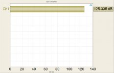
BTW if the last image I posted looks a bit funky, bare in mind it starts THD+N vs a µW so noise tends to dominate =) and by that I mean visually, because at the top of the mountain its still only 0.05% THD+N @ 10µW
these regs get enough bad press as it is, they arent great regs but can be used to good effect and my god are they handy! the effect you mention is there, just be aware of that.
I can understand the compulsion to get rid of any and all potential effects, but myself until the effect actually..has..an effect..on the circuit...i'm good
. for circuits with lower PSRR, I will usually use another regulator rather than adding a pole and lowering the dynamic ability of a regulator already a bit lacking in dynamic ability.BTW if the last image I posted looks a bit funky, bare in mind it starts THD+N vs a µW so noise tends to dominate =) and by that I mean visually, because at the top of the mountain its still only 0.05% THD+N @ 10µW
these regs get enough bad press as it is, they arent great regs but can be used to good effect and my god are they handy! the effect you mention is there, just be aware of that.
Just to illustrate -- 47uF tantalum cap on the output will cause instability (dashed line of Zout is with 100uF aluminum electrolytic):
and a 1uF polyester will cause even more instability:
These aren't simulations.
An externally hosted image should be here but it was not working when we last tested it.
and a 1uF polyester will cause even more instability:
An externally hosted image should be here but it was not working when we last tested it.
These aren't simulations.
thanks, yes like I said its there, be aware of it with the choices of cap size on the output, I never use tantalum, but plenty of X7R ceramics and some allu/polymers in the range of 10mohm.
i'm just saying as yet after many uses, i'm yet to have it make any impact on the actual performance of the circuit, probably due to the fact the local decoupling caps are doing all the work. Any one where it would likely be effected i'm already using another regulator. even the NTD1 of his, based on the Pass D1, but modified, uses them and PSRR is bound to be terrible. its a simple common gate follower, but its a very constant class A load with little dynamic behaviour. I am however in the middle of designing a bipolar TPS47 based reg for it to get the size down and maybe squeeze the last drops out of the circuit, which is already pretty special, with no aberrations.
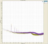
i've asked Owen if he has any impedance vs F plots of his boards. I found the ones I have, but doesnt have a Zout vs F plot, just noise vs F, some FFTs, which would give a hint you would think. i'll link him here, perhaps he'll comment. his are all adjustable regs, not sure if that makes a difference.
hes already posted these on the forum before so hopefully he wont mind.
its not like its a secret patent pending design. they are interesting anyway for their illustration of the 317 vs 337
not the last word in performance, but we all know that, good enough for a lot of loads people often discount them for though IMO
i'm just saying as yet after many uses, i'm yet to have it make any impact on the actual performance of the circuit, probably due to the fact the local decoupling caps are doing all the work. Any one where it would likely be effected i'm already using another regulator. even the NTD1 of his, based on the Pass D1, but modified, uses them and PSRR is bound to be terrible. its a simple common gate follower, but its a very constant class A load with little dynamic behaviour. I am however in the middle of designing a bipolar TPS47 based reg for it to get the size down and maybe squeeze the last drops out of the circuit, which is already pretty special, with no aberrations.
i've asked Owen if he has any impedance vs F plots of his boards. I found the ones I have, but doesnt have a Zout vs F plot, just noise vs F, some FFTs, which would give a hint you would think. i'll link him here, perhaps he'll comment. his are all adjustable regs, not sure if that makes a difference.
hes already posted these on the forum before so hopefully he wont mind.
its not like its a secret patent pending design. they are interesting anyway for their illustration of the 317 vs 337
not the last word in performance, but we all know that, good enough for a lot of loads people often discount them for though IMO
Attachments

What you guys are talking about is a little over my head.. not that I'm saying stop. It's an interesting discussion, and I read it with interest.
I ordered a few different inductors and beads from Digikey yesterday - two each of 10uH, 22uH, 47uH and a 100uH, one toroidal and one ferrite - just to experiment and see the effects of each. hopefully it also solves my problem with the smps switching noise. As I am away from my equipment this weekend, I will post the results early next week. Hopefully this will help other people in my situation.
Thanks again for the suggestions!
Hengy
I ordered a few different inductors and beads from Digikey yesterday - two each of 10uH, 22uH, 47uH and a 100uH, one toroidal and one ferrite - just to experiment and see the effects of each. hopefully it also solves my problem with the smps switching noise. As I am away from my equipment this weekend
, I will post the results early next week. Hopefully this will help other people in my situation.Thanks again for the suggestions!
Hengy
I have been reunited with my equipment!
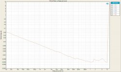
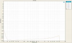
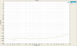
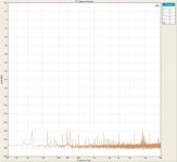
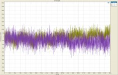
I had time to try the 10uH and 22uH inductors quickly, and take a few pics for comparison. First is the 'raw' input & output. Then the 10uH (this one from Digikey) and the 22uH, all with 3500uF of input caps.
The input cleans up very nicely! I can't really tell if it affects the output all that much - trying it with my amp will tell. There is very little difference between 10uH and 22uH, which doesn't surprise me. i just thought I'd play around with a few different values.
This was very quick, and when I get time - probably tomorrow - I will do a much more thorough test, and of course hook it up to my amp! I will post the results here too.
Hengy
I had time to try the 10uH and 22uH inductors quickly, and take a few pics for comparison. First is the 'raw' input & output. Then the 10uH (this one from Digikey) and the 22uH, all with 3500uF of input caps.
An externally hosted image should be here but it was not working when we last tested it.
An externally hosted image should be here but it was not working when we last tested it.
An externally hosted image should be here but it was not working when we last tested it.
The input cleans up very nicely! I can't really tell if it affects the output all that much - trying it with my amp will tell. There is very little difference between 10uH and 22uH, which doesn't surprise me. i just thought I'd play around with a few different values.
This was very quick, and when I get time - probably tomorrow - I will do a much more thorough test, and of course hook it up to my amp! I will post the results here too.
Hengy
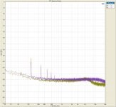
Definitely a substantial improvement on the pre reg side! It is interesting that there is very little change on the post reg side....
But the 47Khz noise spikes on the input were only around 4mV in size so it would appear that the reg is doing its job quite well at this frequency. Any residual noise you are measuring on the output could be due to measurement limitations.
Have you tried a different time base such as 2uS it may allow you to see better the shape of the noise spikes and whether there is still any residual after the reg.
Tony.
Maybe this is of interest? Simple Voltage Regulators Part 1: Noise - [English]
So I hooked everything up late last night, turned on the MP3 player I'm testing the amp with, plugged in some headphones...
and hum. Maybe even a bit worse! It is, however, different, which means i think the inductor did something. Also, the noise is more pronounced on one side, which I didn't notice before.
Now, I checked all the wiring, polarity, etc. I moved things around, but still, hum.
So, going back to what a few of you mentioned earlier, I think the grounding scheme I have (not so carefully) implemented is the problem. Please don't say 'I told you so'.
Tonight I plan on talking the amplifier apart and trying to implement a better grounding system - star ground to be more exact.
I must admit, I'm a bit embarrassed, wasting all the time on inductors while I really should have been paying attention to the grounding system!
Hengy
and hum.
Maybe even a bit worse! It is, however, different, which means i think the inductor did something. Also, the noise is more pronounced on one side, which I didn't notice before.Now, I checked all the wiring, polarity, etc. I moved things around, but still, hum.
So, going back to what a few of you mentioned earlier, I think the grounding scheme I have (not so carefully) implemented is the problem. Please don't say 'I told you so'.
Tonight I plan on talking the amplifier apart and trying to implement a better grounding system - star ground to be more exact.
I must admit, I'm a bit embarrassed, wasting all the time on inductors while I really should have been paying attention to the grounding system!
Hengy
Hum could also be from having enclosed loop areas, making antennas.
Signal input and its ground must stay as close together as possible, everwhere. If wires, twist them tightly together. Or, better, use shielded twisted pair cable, with the shield connected to chassis (NOT to signal ground!) at one end only.
Also, any wire pairs with high current or highly-dynamic current could make transmitting antennas. So twist those tightly together, too. This especially includes power supply wiring.
If using pcbs, either keep ground plane over or under everything or make sure the traces are always very close together, for each type of pair.
Last edited:
- Status
- This old topic is closed. If you want to reopen this topic, contact a moderator using the "Report Post" button.
- Home
- Amplifiers
- Power Supplies
- PS Noise - Solutions and Suggestions