Hi everyone,
I am in the process of building a np100v12 headphone amp Link. Right now, most of it is on a breadboard - and works - except that there is a tiny bit of hf noise from the power supply.
I have included many diagrams and screen shots from my scope, in hopes that it aids in finding a solution!
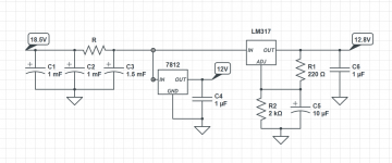
I am using an older laptop smps power supply - 18.5V, 3A. This is, right now, followed by 3500uF of low-ESR (Nichicon HE) E-caps, and a 0.1uF ceramic. Next are two voltage regulators: a 7812 for the heater, and a LM317 for the rest of the circuit. Both of these are followed by 1uF low-ESR ceramics. Also, the LM317 has a 10uF E-cap on the adj pin.
This is the schematic of the filtering and regulation after the input from the smps:
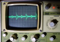
This is the raw input and from the smps (top, yellow, 50mV/div), and the output from the LM317 (bottom, blue, 5mv/div). Only C5. Circuit is loaded with 150mA - about 1/4 of what the final circuit will use.
Very noisy input, and still lots of HF noise on the output.
And this is the input and output with 3.5mF input caps and 0.1uF output caps. Both are now 5mV/div. Circuit is loaded with 150mA:
2mV/div
Much cleaner, but upon close up, still much too noisy for audio. It is the best I could get. Adding more caps, both on the input and output didn't help
Finally, after adding adding the heater on the 7812 output:
Doesn't really add noise, but increases the frequency a little (?).
The HF noise doesn't surprise me, especially after reading this article.
At this point, I figure I need a LC filter after the smps. Trouble is, I know very little about inductors. For some reason, it was never even mentioned in my university courses
From what I've learned on the internet, I propose putting around 10-20uH in series, after the smps, and before the input caps. Would something like this inductor work? According to an online calculator, this gives a cutoff frequency of 220Hz, and about -20dB @1KHz.
Any suggestions would be much appreciated, especially on the design of the LC filter!
Thanks,
Hengy
I am in the process of building a np100v12 headphone amp Link. Right now, most of it is on a breadboard - and works - except that there is a tiny bit of hf noise from the power supply.
I have included many diagrams and screen shots from my scope, in hopes that it aids in finding a solution!
I am using an older laptop smps power supply - 18.5V, 3A. This is, right now, followed by 3500uF of low-ESR (Nichicon HE) E-caps, and a 0.1uF ceramic. Next are two voltage regulators: a 7812 for the heater, and a LM317 for the rest of the circuit. Both of these are followed by 1uF low-ESR ceramics. Also, the LM317 has a 10uF E-cap on the adj pin.
This is the schematic of the filtering and regulation after the input from the smps:
An externally hosted image should be here but it was not working when we last tested it.
This is the raw input and from the smps (top, yellow, 50mV/div), and the output from the LM317 (bottom, blue, 5mv/div). Only C5. Circuit is loaded with 150mA - about 1/4 of what the final circuit will use.
An externally hosted image should be here but it was not working when we last tested it.
Very noisy input, and still lots of HF noise on the output.
And this is the input and output with 3.5mF input caps and 0.1uF output caps. Both are now 5mV/div. Circuit is loaded with 150mA:
An externally hosted image should be here but it was not working when we last tested it.
2mV/div
An externally hosted image should be here but it was not working when we last tested it.
Much cleaner, but upon close up, still much too noisy for audio. It is the best I could get. Adding more caps, both on the input and output didn't help
Finally, after adding adding the heater on the 7812 output:
An externally hosted image should be here but it was not working when we last tested it.
Doesn't really add noise, but increases the frequency a little (?).
The HF noise doesn't surprise me, especially after reading this article.
At this point, I figure I need a LC filter after the smps. Trouble is, I know very little about inductors. For some reason, it was never even mentioned in my university courses
From what I've learned on the internet, I propose putting around 10-20uH in series, after the smps, and before the input caps. Would something like this inductor work? According to an online calculator, this gives a cutoff frequency of 220Hz, and about -20dB @1KHz.
Any suggestions would be much appreciated, especially on the design of the LC filter!
Thanks,
Hengy
Thanks for your reply knutn,
Not sure if you took a look at this link: Using 3-pin regulators off-piste: part 2 It shows that smps switching noise can pass through a lm317 regulator! I am fairly new to p2p on perfboard, so the less components the better.
I'm pretty set on building a LC filter, and that's what I need help on. The long post was meant to show what I had already tried, and that I'm not just asking for help without trying anything myself.
The above link suggests an inductor preceding the lm317, but the only detail it gives is that it should be "10s of uH". I think I need a little guidance before going into that unknown! (unless I can just randomly start plunking in inductors in series after the smps without ill effects?)
Thanks,
Hengy
You might try using an RC or CRC filter before the linear regulators. The spiky noise from the SMPS is probably too much for the reg to filter on its own. Caps alone are not useful for noise filtering - you need a low-pass filter, RC or LC, but with an LC filter you can inadvertently form high frequency resonances so try RC or CRC configuration first.
tauro0221,
I did try combinations of different sized ceramic and Ecaps, all low ESR types.
Here is 100uF and 470uF Ecaps, as well as an additional 10uF ceramic cap on the output, respectively:
No additional capacitance makes a difference.
I have never built a xformer-based power supply, and I don't think I want to start on this project.
Thanks,
Hengy
I did try combinations of different sized ceramic and Ecaps, all low ESR types.
Here is 100uF and 470uF Ecaps, as well as an additional 10uF ceramic cap on the output, respectively:
An externally hosted image should be here but it was not working when we last tested it.
An externally hosted image should be here but it was not working when we last tested it.
An externally hosted image should be here but it was not working when we last tested it.
No additional capacitance makes a difference.
I have never built a xformer-based power supply, and I don't think I want to start on this project.
Thanks,
Hengy
The size of the resistor R depends on how much current you are going to draw. The higher the value you can choose, the better the filtering.You might try using an RC or CRC filter before the linear regulators.
Attachments
The regulators does nothing to remove this high frequency ripple, it is beyound their bandwidth by far.
The noise has mainly two different sources:
the ripple up and down in a triangular shape is due to the current flow through the SMPS inductors, this ripple current multplies with ESR in the output cap etc to give this ripple voltage. Thus we can learn that the SMPS operates at about 50 kHz (it is late and my eyes are tired...)
Second is spikes, that is due to leakage/stray inductance (nH is enough) in the high current switching path. There is probably some ringing in the tens of MHz due to parasitic capacitance/inductance here and there in it to.
First is best removed by an extra LC filter, say 10uH and 100uF.
Second is harder, because any stray capacitance couples this . Best is probably a very low selfinductance cap (SMD ceramic) and then adding ferrite beads to both the positive and ground lead of the output, causing a higher impendance at high frequency. Beads, beads, beads...
The size of the resistor R depends on how much current you are going to draw. The higher the value you can choose, the better the filtering.
knutn,
I thought about trying a RC filter, however, using a higher value resistor (> 8 Ohms) drops more than 5V at 700mA, so then the regulators don't have enough headroom. If I use smaller resistors, it would provide less than 5dB attenuation. I'm not sure if that would be enough
This was based on rough calculations, which came pretty close to an online calculator I found
rikkitikkitavi,
I will purchase some inductors and ferrite beads asap, and try those. Is there any reason not to try a larger inductor and/or cap?
I am curious though, if MHz ringing is what is causing the noise I hear on my headphones? I have heard of harmonics, and even studied a little bit about it in post-sec, but surely it is all well above the audible range? I would never be able to hear a MHz signal.
whizgeek,
Even if they do go away with a higher load, I have no justifiable means of continuously putting that load on the smps while using the headphone amp. (I am not one of those who like a blindingly bright, 50W blue LED on the front of their electronics!
) My regulators get warm enough without having more heat dissipated into the enclosure.I know this is not what you are asking (and I can't help with that as I have no experience with LC filters in Power Supplies) however there are a couple of things that I think need to be raised anyway
1. Your input to output differential is only 4.7V The LM317 performs best when the in to out differential is 5V or higher. How much difference that additional 0.3V will make though is probably academic. However if you reduce it further by doing a CRC then it *may* actually make the situation worse (even if the noise before the reg is lower!! certainly that was what I observed with my testing!
2. Using low esr caps on the output of an LM317 is a no-no unless you add some series resistance in yourself. I'd suggest bumping up the output cap to say 47uF with maybe around 0.5ohms in series with it. low esr cap on the output will most likely result in a resonance within the audio range.
Tony.
1. The LM317 performs best when the in to out differential is 5V or higher.
You learn something everyday! (and today was the first day of classes for the new semester, so I was getting worried
 )
)I am planning on trying a LC filter first. It will reduce the voltage by less than 0.5V according to LTSpice.
2. Using low esr caps on the output of an LM317 is a no-no unless you add some series resistance in yourself.
I assumed low esr caps were better in every part of the power supply.
Thank you for your suggestions and ideas! I will definitely test them out at some point. I am interested to see if I can recreate both effects.
Hengy
You learn something everyday! (and today was the first day of classes for the new semester, so I was getting worried
I am planning on trying a LC filter first. It will reduce the voltage by less than 0.5V according to LTSpice.
I assumed low esr caps were better in every part of the power supply.
Thank you for your suggestions and ideas! I will definitely test them out at some point. I am interested to see if I can recreate both effects.
Hengy
Careful with the low-ESRs -- the equivalent output impedance of yer typical 3 terminal regulator is inductive with a tiny resistance in series, so adding a low-ESR capacitor is a fine way to make a series resonant circuit. This is a case where the cheap part is a better choice.
Details of grounding will affect the result. No amount of filtering will deal with a noisy ground.
Do not ignore this in your quest for filtering! And not just grounding, general layout- HF signals have a tendency to couple in unexpected ways.
Additionally, you want to think about both differential and common mode noise.
+1 to DF96 and SY. The point on the board you put your earth probe from your scope will make big differences to the apparent noise levels as well!! Try moving it around a bit and you should see
Additionally, I know this may sound silly, but try doing some measurements with the power turned off as well, just for a baseline. I discovered that there were all sorts of sources of the noise when testing my LM317 PS. Getting reliable measurements at the low levels you are trying is actually very difficult!
Turn off every device in the house that you can. I had noise at 833Khz (see attached pic) pre reg (at 60mV p2p) which turned out to be coming from a PC (or it's monitor) powersupply about 10M away!! Not everything may be coming from whence you think
Tony.
Attachments
- Status
- This old topic is closed. If you want to reopen this topic, contact a moderator using the "Report Post" button.
- Home
- Amplifiers
- Power Supplies
- PS Noise - Solutions and Suggestions