hello
i am making a power supply for my LM1876 chip amp.
here is the schematic im using:
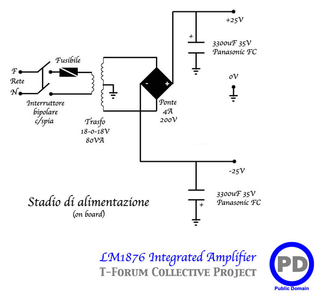
the transformer i have is wired like this (according to the datasheet)
so.... which wire goes where to the bridge rectifier? the red/brown?
really dont want to fry it up, so any advice would be greatly appreciated!
thanks
úlfur
i am making a power supply for my LM1876 chip amp.
here is the schematic im using:
the transformer i have is wired like this (according to the datasheet)
An externally hosted image should be here but it was not working when we last tested it.
so.... which wire goes where to the bridge rectifier? the red/brown?
really dont want to fry it up, so any advice would be greatly appreciated!
thanks
úlfur
Join the red and brown, that's is your 0v, where you put the ground of capacitors
the green and blue goes for the rectifier
the green and blue goes for the rectifier
If you are unsure then use a bulb tester (low wattage mains filament bulb) in series with the mains. That will limit current and enable you to check it safely. The bulb should be out (not lit) when its correct and all DC voltages will be correct too.

thanks for your replies!
alas, i hooked it up like you suggested - and POOF! - my LM1876 chip blew up. i have no clue what could have gone wrong.
i am using this schematic;
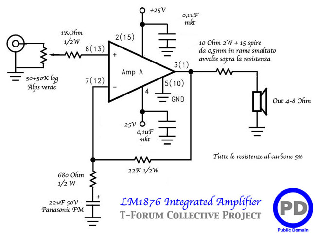
any thoughts?
alas, i hooked it up like you suggested - and POOF! - my LM1876 chip blew up. i have no clue what could have gone wrong.
i am using this schematic;
any thoughts?
Try measuring the DC voltages from the power supply. Just check that you do have +/- 25V with respect to 0V.
Have you got bridge rectifier the right way around? The LM1876 would certainly fry if you inadvertently connect + to - and - to +.
Have you got bridge rectifier the right way around? The LM1876 would certainly fry if you inadvertently connect + to - and - to +.
If all is well just recheck your soldering very carefully - look for any shorts.
Also check your speakers and their cabling for shorts.
Also check your speakers and their cabling for shorts.
You're going to have to replace the chip and power it up with the bulb tester to prevent damage. And NO speakers connected either.
I see the diagram doesn't show a zobel network... very unusual... I would certainly add one. Say 6.8 ohm and a 0.1uf cap from the output to ground.
I see the diagram doesn't show a zobel network... very unusual... I would certainly add one. Say 6.8 ohm and a 0.1uf cap from the output to ground.
- Status
- Not open for further replies.
- Home
- Amplifiers
- Power Supplies
- toroidal transformer wire identification!