Yes.
Look up online
"Full Wave Rectifier"
and
"Bridge Rectifier"
You will not be able to get + & - from a single secondary.
There are tricks to get a "center" point, but that's not probably something you want to do. Are you sure you have ONLY a single secondary??
Two wires? Or Three? Or four?
Look up online
"Full Wave Rectifier"
and
"Bridge Rectifier"
You will not be able to get + & - from a single secondary.
There are tricks to get a "center" point, but that's not probably something you want to do. Are you sure you have ONLY a single secondary??
Two wires? Or Three? Or four?
Elliott Sound Products - Linear Power Supply Design
I suggest that you read the entire article.
I suggest that you read the entire article.
Yes.
You will not be able to get + & - from a single secondary.
There are tricks to get a "center" point, but that's not probably something you want to do. Are you sure you have ONLY a single secondary??
Two wires? Or Three? Or four?
You can get two rails from a single transformer using half wave rectification to get each supply.
I know the picture shows two windings but treat as one for your purpose.
An externally hosted image should be here but it was not working when we last tested it.
Last edited:
Get yourself another identical transformer.
Or
Get yourself a proper transformer for the job (which you did not say what it is). Imo half wave rectifier supplies are not normally a great idea...
You might say what your application is, so that folks might give you a better bit of input?
Or
Get yourself a proper transformer for the job (which you did not say what it is). Imo half wave rectifier supplies are not normally a great idea...
You might say what your application is, so that folks might give you a better bit of input?
Why? Because you need twice the capacitance?Imo half wave rectifier supplies are not normally a great idea...
There is another reason.
Here is an example.
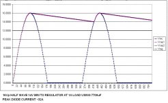
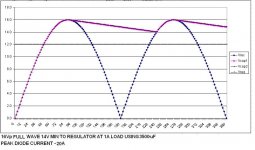
You have 16Vp from either a half wave or full wave rectifier.
You need 2V "headroom" on a 12V regulator at 1A (14V min)
With a full wave rectifier the capacitor only needs to be 3500uF and gets recharged at twice the line frequency rate. During the time this value of capacitor needs to be recharged the peak diode (and transformer) current is about 20A.
With a half wave rectifier the capacitor needs to be 7700uF and gets recharged at the line frequency rate. During the time this value of capacitor needs to be recharged the peak diode (and transformer) current is about 32A.
The capacitor needs to be bigger to supply the charge to the regulator for a longer period of time. Slightly longer than twice as long so slightly more than twice as large.
The larger the capacitor, the more current it takes to recharge it in the same amount of time.
Hope that helps explain what is happening and why half wave rectification is rarely used.
It is used more with lower current applications. IMO
Here is an example.
You have 16Vp from either a half wave or full wave rectifier.
You need 2V "headroom" on a 12V regulator at 1A (14V min)
With a full wave rectifier the capacitor only needs to be 3500uF and gets recharged at twice the line frequency rate. During the time this value of capacitor needs to be recharged the peak diode (and transformer) current is about 20A.
With a half wave rectifier the capacitor needs to be 7700uF and gets recharged at the line frequency rate. During the time this value of capacitor needs to be recharged the peak diode (and transformer) current is about 32A.
The capacitor needs to be bigger to supply the charge to the regulator for a longer period of time. Slightly longer than twice as long so slightly more than twice as large.
The larger the capacitor, the more current it takes to recharge it in the same amount of time.
Hope that helps explain what is happening and why half wave rectification is rarely used.
It is used more with lower current applications. IMO
Attachments
There is another reason.
Here is an example.
You have 16Vp from either a half wave or full wave rectifier.
You need 2V "headroom" on a 12V regulator at 1A (14V min)
With a full wave rectifier the capacitor only needs to be 3500uF and gets recharged at twice the line frequency rate. During the time this value of capacitor needs to be recharged the peak diode (and transformer) current is about 20A.
With a half wave rectifier the capacitor needs to be 7700uF and gets recharged at the line frequency rate. During the time this value of capacitor needs to be recharged the peak diode (and transformer) current is about 32A.
The capacitor needs to be bigger to supply the charge to the regulator for a longer period of time. Slightly longer than twice as long so slightly more than twice as large.
The larger the capacitor, the more current it takes to recharge it in the same amount of time.
Hope that helps explain what is happening and why half wave rectification is rarely used.
It is used more with lower current applications. IMO
Very nice...
Yes, so more filtering required and bigger peak currents. Still, this is the simplest solution to the problem and likely to be suitable.
When the OP asked how to use an existing transformer for a particular application, an answer of "get a different one" isn't really being all that helpful...
When the OP asked how to use an existing transformer for a particular application, an answer of "get a different one" isn't really being all that helpful...
kinda depends on what he is powering, doesn't it?
since low VA transformers are not expensive, i would go for it.
and high VA applications don't usually go well with half wave - and more caps cost money
too... so there is a balance to be found.
Maybe the OP might say what he is going to run with it?
since low VA transformers are not expensive, i would go for it.
and high VA applications don't usually go well with half wave - and more caps cost money
too... so there is a balance to be found.
Maybe the OP might say what he is going to run with it?
NigelWright got it exactly correct: Use of a half-wave voltage-doubler is the cheap-n-dirty way to get the voltages being looked for, -21 : 0 : +21 volts (before correction for peak-over-RMS)
NOTE though - it is definitely half-wave rectification, so the capacitors should be rather large to hold enough juice between waves. And also beware - BOTH the positive and the negative supply rails need independent regulators. And beware - that regulators that are complimentary are often happy to short the whole damned thing out if attached to the same heat sink.
GoatGuy
- Status
- This old topic is closed. If you want to reopen this topic, contact a moderator using the "Report Post" button.
- Home
- Amplifiers
- Power Supplies
- Help with transformers