Preparing Zimmer layout - part three
Dx Supply - Zimmer layout - start produce & test - part THREE - YouTube
regards,
Carlos
Dx Supply - Zimmer layout - start produce & test - part THREE - YouTube
regards,
Carlos
Assembling Dx Supply - part four
Dx Supply - Zimmer layout - start produce & test - part FOUR - YouTube
regards,
Carlos
Dx Supply - Zimmer layout - start produce & test - part FOUR - YouTube
regards,
Carlos
Zimmer layout was tested and approved
Zimmer layout approved, aprovado o layout do alemão - YouTube
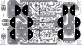
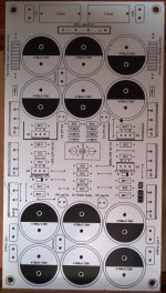
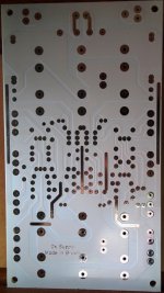
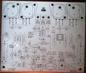
Soon he will publish all images needed for you to etch your own Dx Supply at home.
Juan Vargas is also testing his layout...he will do the same..and bother will order manufacturer to produce their pcboards.
regards,
Carlos
Zimmer layout approved, aprovado o layout do alemão - YouTube
Soon he will publish all images needed for you to etch your own Dx Supply at home.
Juan Vargas is also testing his layout...he will do the same..and bother will order manufacturer to produce their pcboards.
regards,
Carlos
Now with heatsinks - assemble and test part five - final
Dx Supply - Zimmer layout - start produce & test - part FIVE - YouTube
regards,
Carlos
Dx Supply - Zimmer layout - start produce & test - part FIVE - YouTube
regards,
Carlos
Studying the Dx Supply, the stabilization
Dx Supply study, estudo da fonte Dx - YouTube
regards,
Carlos
Dx Supply study, estudo da fonte Dx - YouTube
regards,
Carlos
Dx Supply, the first model, earlier model
This circuit was developed based into Ampex power supply, used to Video Tape Recorders, Open Reel Professional Video Tape Recorders, in the seventies.
I am using this circuit since they release, i have assemble more than 60 units, some sold to Radio Amateurs..no one complained and this is happening this last 43 years... a long time proving reliability.
This circuit was not able to face the huge current the Dx Super A drains at 2 ohms...also not able to face two channels at 4 ohms....to use 4 ohms we are forced to build two circuits, one supply to each power amplifier channel, reason why i decide to make it stronger and a new model, with more transistors, more capacitors and demanding bigger heatsinks was developed, tested and approved yesterday the Zimmer layout.
Juan Vargas layout is being tested and soon we gonna have results and layouts published after approval.
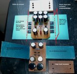
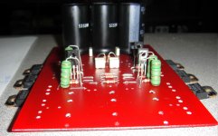
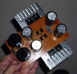
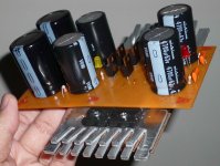
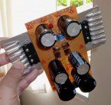
This circuit, shown into the pictures, is the old one, the first model, the first one, the smaller one...and it is suggested if you will operate 8 ohms only, then it will be able to feed two channels at same time, full power at 8 ohms and even with 10 percent distortion the supply will survive.
But heatsinks must be bigger than this one show that is there only to produce a nice picture..it is too much small....it is there for demonstration purposes only.
To use it you should plug 33 plus 33 volts alternated, with center tap, a 350 to 400 watts power transformer, or 400 VA unit.... that rectified and filtered will result in 46.5 volts DC positive and negative.
You can decrease the wattage ratio or the AC voltage, but do not increase it because power dissipation into the series pass transistors will increase and will put the supply into the risk to be damaged... decreasing voltage is allowable, but understand the output power will also be reduced because you should adjust to have 4.5 volts difference in between the regulator input (rectifier and filter side) to the regulator output (the output condensers)..this means you should adjust to read 4.5 volts in between colector and emitter in the series pass transistors, your multimeter probe points will be at the series pass transistor coletor and emitter to adjust the output voltage that gonna be dependable from the input voltage.
If your supply is 30 plus 30 volts, as an example, your DC rectified and filter will result in something around 42 volts..then you should adjust your output voltage to 37.5 volts and you 8 ohms power will drop from 80 to 55 watts RMS. to each channel, THD 0.003%
You should adjust the output to 42 volts positive and negative rails (never more than that because of the BD139 and BD140)
Heatsink area exposed to the air must be (4.5 volts from colector to emitter or from regulator input to regulator output) 450 square centimeters if you consider only one face (not two faces)..this means a 21 by 21 centimeters aluminum blade (if flat) to each rail..... something around 55 watts heatsink to each rail.
Rectifier bridge should be 20 amperes minimum.
Transistors suggested are the bigger one you can find.... MJL4281A and complementary are the most tested ones that proved to be reliable.
Naturally you can use it together other amplifiers, not only Dx Super A or Dx models, it is just a series pass regulator with error amplifier, a very standard and often used circuit, very popular circuit that can be used together any amplifier...but of course, you should respect the input voltage, also output voltage and recalculate to check if the supply can face your amplifier.
Imagine you adjust it to 14 volts because of an automotive amplifier.... input is 46 volts.... voltage drop into the series pass transistor (one rail thinking) is 36 volts multiplied by 20 amperes (automotive power amplifier)..then the power into the series pass transistors gonna be 720 watts to each rail ( means 1440 considering both rails driven) ..the rectifier will explode, the series pass transistors will melt and the heatsink to use will be to the size of a small refrigerator...so..this supply will not be good to this kind of application...a SMPS is the suggested supply to this automotive power amplifier.
This supply was designed, calculated, assembled and tested, to feed Dx Super A amplifier...this one able to face 400 watts consumption (total positive rail plus negative rail).
The new supply can face 1000 watts easy (both rails), of course if you use correct output transistors, correct transformer, rectifiers, filters and heatsinks.
So, it can be used to several tasks, but you should engage brain in advance or start a conversation with uncle charlie.
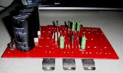
This one, in the picture below is 400 watts only...and with these heatsinks it can manage much less than that...the small heatsinks are there only to produce a nice image, a nice picture..they are too much small.
Two of these TO220 transistors should have small heatsinks not shown into the image posted...the left side ones considering the left side image...the rigth side ones are the error amplifier, and the left side ones are composing the output in a darlington connection.
This supply uses power equalizing resistors into the series pass transistor's emitters..value is 0.1 ohms suggested, but you can use 0.22 ohms too...in an emergency you can use 0.33 ohms..but the best option is the 0.1 ohms resistor.
Watch videos of my channel, they are made because of you, in portuguese and english and they are much more rich in information than typed words can be..there you have audio and video...much richer information you can have there.
regards,
Carlos
This circuit was developed based into Ampex power supply, used to Video Tape Recorders, Open Reel Professional Video Tape Recorders, in the seventies.
I am using this circuit since they release, i have assemble more than 60 units, some sold to Radio Amateurs..no one complained and this is happening this last 43 years... a long time proving reliability.
This circuit was not able to face the huge current the Dx Super A drains at 2 ohms...also not able to face two channels at 4 ohms....to use 4 ohms we are forced to build two circuits, one supply to each power amplifier channel, reason why i decide to make it stronger and a new model, with more transistors, more capacitors and demanding bigger heatsinks was developed, tested and approved yesterday the Zimmer layout.
Juan Vargas layout is being tested and soon we gonna have results and layouts published after approval.
This circuit, shown into the pictures, is the old one, the first model, the first one, the smaller one...and it is suggested if you will operate 8 ohms only, then it will be able to feed two channels at same time, full power at 8 ohms and even with 10 percent distortion the supply will survive.
But heatsinks must be bigger than this one show that is there only to produce a nice picture..it is too much small....it is there for demonstration purposes only.
To use it you should plug 33 plus 33 volts alternated, with center tap, a 350 to 400 watts power transformer, or 400 VA unit.... that rectified and filtered will result in 46.5 volts DC positive and negative.
You can decrease the wattage ratio or the AC voltage, but do not increase it because power dissipation into the series pass transistors will increase and will put the supply into the risk to be damaged... decreasing voltage is allowable, but understand the output power will also be reduced because you should adjust to have 4.5 volts difference in between the regulator input (rectifier and filter side) to the regulator output (the output condensers)..this means you should adjust to read 4.5 volts in between colector and emitter in the series pass transistors, your multimeter probe points will be at the series pass transistor coletor and emitter to adjust the output voltage that gonna be dependable from the input voltage.
If your supply is 30 plus 30 volts, as an example, your DC rectified and filter will result in something around 42 volts..then you should adjust your output voltage to 37.5 volts and you 8 ohms power will drop from 80 to 55 watts RMS. to each channel, THD 0.003%
You should adjust the output to 42 volts positive and negative rails (never more than that because of the BD139 and BD140)
Heatsink area exposed to the air must be (4.5 volts from colector to emitter or from regulator input to regulator output) 450 square centimeters if you consider only one face (not two faces)..this means a 21 by 21 centimeters aluminum blade (if flat) to each rail..... something around 55 watts heatsink to each rail.
Rectifier bridge should be 20 amperes minimum.
Transistors suggested are the bigger one you can find.... MJL4281A and complementary are the most tested ones that proved to be reliable.
Naturally you can use it together other amplifiers, not only Dx Super A or Dx models, it is just a series pass regulator with error amplifier, a very standard and often used circuit, very popular circuit that can be used together any amplifier...but of course, you should respect the input voltage, also output voltage and recalculate to check if the supply can face your amplifier.
Imagine you adjust it to 14 volts because of an automotive amplifier.... input is 46 volts.... voltage drop into the series pass transistor (one rail thinking) is 36 volts multiplied by 20 amperes (automotive power amplifier)..then the power into the series pass transistors gonna be 720 watts to each rail ( means 1440 considering both rails driven) ..the rectifier will explode, the series pass transistors will melt and the heatsink to use will be to the size of a small refrigerator...so..this supply will not be good to this kind of application...a SMPS is the suggested supply to this automotive power amplifier.
This supply was designed, calculated, assembled and tested, to feed Dx Super A amplifier...this one able to face 400 watts consumption (total positive rail plus negative rail).
The new supply can face 1000 watts easy (both rails), of course if you use correct output transistors, correct transformer, rectifiers, filters and heatsinks.
So, it can be used to several tasks, but you should engage brain in advance or start a conversation with uncle charlie.
This one, in the picture below is 400 watts only...and with these heatsinks it can manage much less than that...the small heatsinks are there only to produce a nice image, a nice picture..they are too much small.
Two of these TO220 transistors should have small heatsinks not shown into the image posted...the left side ones considering the left side image...the rigth side ones are the error amplifier, and the left side ones are composing the output in a darlington connection.
This supply uses power equalizing resistors into the series pass transistor's emitters..value is 0.1 ohms suggested, but you can use 0.22 ohms too...in an emergency you can use 0.33 ohms..but the best option is the 0.1 ohms resistor.
Watch videos of my channel, they are made because of you, in portuguese and english and they are much more rich in information than typed words can be..there you have audio and video...much richer information you can have there.
regards,
Carlos
Attachments
Last edited:
Thank you very much Uncle Charlie...
With all the efforts and hard work you have contributed to produce this DX supply deserves another credits from all diy'ers like me, Great Job Uncle Charlie...
BTW, Can you post the approved Zimmer layout in jpg. file so we can have a try...")
Thanks for sharing....
Regards,
With all the efforts and hard work you have contributed to produce this DX supply deserves another credits from all diy'ers like me, Great Job Uncle Charlie...
BTW, Can you post the approved Zimmer layout in jpg. file so we can have a try...
Thanks for sharing....
Regards,
Last edited:
Brazilian files from Zimmer about the Dx Supply
You can find into the Dx Super A thread, files about the amplifier.
Here you have a link to all stuff:
https://mega.co.nz/#!5lFFQSRb!XVRt4TNUaMYqtVgLzCbmUGNqctgy5uW6LFBkI6LeEGg
But i will upload each file to the forum too.
regards,
Carlos
You can find into the Dx Super A thread, files about the amplifier.
Here you have a link to all stuff:
https://mega.co.nz/#!5lFFQSRb!XVRt4TNUaMYqtVgLzCbmUGNqctgy5uW6LFBkI6LeEGg
But i will upload each file to the forum too.
regards,
Carlos
Attachments
Pcboards, for Brazil, now in production
We are waiting...all tested... all finished..now it is time to relax.
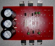
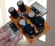
Pictures is the former supply, the first one made..the smaller one...very nice too.
ATTENTION!
read the entire thread before assemble or install this supply together your amplifiers..there are several limits that you must know..it is not an Universal Supply that you can use anyway and anywhere, there are limits of voltage, current and as consequence limits of power.... read the ENTIRE thread in advance to build.
regards,
Carlos
We are waiting...all tested... all finished..now it is time to relax.
Pictures is the former supply, the first one made..the smaller one...very nice too.
ATTENTION!
read the entire thread before assemble or install this supply together your amplifiers..there are several limits that you must know..it is not an Universal Supply that you can use anyway and anywhere, there are limits of voltage, current and as consequence limits of power.... read the ENTIRE thread in advance to build.
regards,
Carlos
Attachments
Last edited:
Naturally i can help you if you have an special case
For instance:
- I have a 44 volts AC supply and i want to feed two channels of my amplifier that can put out XXX watts RMS at 8 ohms, YYY watts RMS at 4 ohms and ZZZ watts RMS at 2 ohms all specifications at less than 1 percent harmonic distortion...and i want to adjust the supply output to 46.3 volts DC, so, what gonna be the limits?... and what the heatsink size in area exposed to the air (all fins added one to the other, creating a single flat virtual fin)
- Can i operate 4 ohms and 2 ohms?
I can try to help you on that...just let me know.
But send me all informations you have..transformer VA or Watts, how many transformers you gonna use..how many Dx Supply circuits you intend to use...your mains fuse value (to the transformer primary), your power amplifier fuses values, and the kind of music you like and the application for the amplifier....it is for parties?... for sound instruments?... will be connected to organ or synthesizer,... do you use to play really loud.... do you accept some distortion?.... all informations are usefull to derate the supply performance to the worst case scenario.
I cannot make this study for hundreds of persons..but i can make for a few guys.... all data is important..schematics of amplifiers and all details you can provide me will be helpfull to re create the "scenery".
carlos.eugenio1951@yahoo.com
regards,
Carlos
Last edited:

Ahahahahahahh!.... negative.... only Coca Cola
This Peroxide is the most strong we can obtain here...then we mix with Muriatic Acid and we use the mix to corrode copper to make pcboards,
Muriatic Aicid is Hydrochloric Acid
Here you can see something about:
How to make circuit boards fast - Dx way - YouTube
regards,
Carlos
This Peroxide is the most strong we can obtain here...then we mix with Muriatic Acid and we use the mix to corrode copper to make pcboards,
Muriatic Aicid is Hydrochloric Acid
Here you can see something about:
How to make circuit boards fast - Dx way - YouTube
regards,
Carlos
It is not mine.... Ampex made it.... i just used these last 40 years
Deeply tested....anything critical..you can replace transistors by thousands of other models, also resistors are not critical, zener is not critical, trimpot is not critical...transformer and voltages also not critical (must by higher than the zener...usually zener is one third of the input voltage), condensers not critical.
This is wonderfull, i have assembled and sold to Radio Amateurs (i am a HAM too) and nobody have ever complained.
Sony, and all audio brands have used in past amplifiers..then they decided to remove the stuff because increase cost and the audible advantage is not perceived by the average listener.
The Dx Super A is mine...not from the scratch...was a step by step evolution (several models) based into Doctor Self Blameless.
Blameless was alike a scratch, (a skeleton a basic structure, a topology, an idea devoid of details) something basic with awesome low THD, i have tweaked to sonics changing a lot of things in a step by step evolution, and this took almost 6 years long.. the starting point, the first 4 years surfing this forum, was dedicated to develop something alike Aksa 55 from Aspen Amplifiers, an abandoned design now a days, Hugh Dean and I have published the schematic, the basic schematic without some secrets that i have not used too.... well... was very basic, and Hugh Dean have made much better things since 2000.
regards,
Carlos
Last edited:
- Status
- This old topic is closed. If you want to reopen this topic, contact a moderator using the "Report Post" button.
- Home
- Amplifiers
- Power Supplies
- Dx Supply, output adjustable, stabilized power supply