Now in development...one unit (prototype) already assembled and tested, and a pcboard layout starting to be developed.
Juan Vargas and other folks may help producing decent layouts using software.
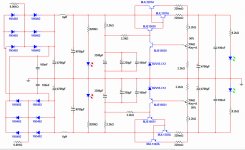
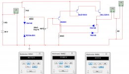
It uses three output pairs (not shown in the schematic), able to 150 watts each rail (easy), stabilized within 2.5% .
This depends on your transformer power, of course..no magic allowable here, it is an analogue supply.
It was made (the style, the frame, the idea, the topology) down the seventies by Ampex to power 2 inches tape video tape recorders..also used by Sony and others.
A very good, very simple, very reliable supply i am using since the seventies.
I have build several and worked together HAM transceivers sucking 340 watts of power from the mains.... delivering 13.8 volts and 22 amperes in the output with wonderfull regulation to SSB transmitters.
The speed of the reaction into the error amplifier is adjustable by a single electrolitic condenser..you can have it fast or slow decay of voltage...quick reaction or not, depending your use..to class A amplifier you do not need all that quick response as current does not variates too much.. 50 percent to 100 percent only..when other amplifiers goes from 10 percent to 100 percent of consumption.
Many units assembled..never had a single complain..it works, is reliable and you can adjust your output voltage from the zener diode used (usually one third of the output maximum output voltage, to the supply maximum output voltage..in our case is more or less 14 to 43 volts.
You adjust your output using two separated potentiometers..this way you can adjust the output voltage the way you want having two supplies...and you can use one, or other or two of them same time (symetrical)
It saves electrolitic condenser capacity because use a modified (Dx Patent 0000000 registered in the book 0000, page 0000, line 0000) capacitance multiplier.
A video about:
Dx Supply - Home board will be prepared - YouTube
regards,
Carlos
Juan Vargas and other folks may help producing decent layouts using software.
It uses three output pairs (not shown in the schematic), able to 150 watts each rail (easy), stabilized within 2.5% .
This depends on your transformer power, of course..no magic allowable here, it is an analogue supply.
It was made (the style, the frame, the idea, the topology) down the seventies by Ampex to power 2 inches tape video tape recorders..also used by Sony and others.
A very good, very simple, very reliable supply i am using since the seventies.
I have build several and worked together HAM transceivers sucking 340 watts of power from the mains.... delivering 13.8 volts and 22 amperes in the output with wonderfull regulation to SSB transmitters.
The speed of the reaction into the error amplifier is adjustable by a single electrolitic condenser..you can have it fast or slow decay of voltage...quick reaction or not, depending your use..to class A amplifier you do not need all that quick response as current does not variates too much.. 50 percent to 100 percent only..when other amplifiers goes from 10 percent to 100 percent of consumption.
Many units assembled..never had a single complain..it works, is reliable and you can adjust your output voltage from the zener diode used (usually one third of the output maximum output voltage, to the supply maximum output voltage..in our case is more or less 14 to 43 volts.
You adjust your output using two separated potentiometers..this way you can adjust the output voltage the way you want having two supplies...and you can use one, or other or two of them same time (symetrical)
It saves electrolitic condenser capacity because use a modified (Dx Patent 0000000 registered in the book 0000, page 0000, line 0000) capacitance multiplier.
A video about:
Dx Supply - Home board will be prepared - YouTube
regards,
Carlos
Attachments
Something more about this supply.
Dx Super A - Dx Voltage regulator - YouTube
Here in portuguese only:
Fonte Dx tá pronta sim - YouTube
regards,
Carlos
Dx Super A - Dx Voltage regulator - YouTube
Here in portuguese only:
Fonte Dx tá pronta sim - YouTube
regards,
Carlos
A little bit more comments
I will explain how it works soon.
Now i gonna work to build and test the new pcboard.
Dx Supply more comments - YouTube
regards,
Carlos
I will explain how it works soon.
Now i gonna work to build and test the new pcboard.
Dx Supply more comments - YouTube
regards,
Carlos
This is very helpfull, for instance
You want to build a Class A power amplifier that needs 22 plus 22 volts DC... and you already have a 56 plus 56V supply, rectified and filtered...then you enter this DC voltage after the rectifiers, into the DC input section, and adjust to the voltage you want.
Much better if you have a power transformer measuring 40 plus 40 volts AC..then you can plug this AC voltage directly into the diodes and will have an adjustable power supply able to go from 15 to almost 56 volts each rail.
You can adjust and ready to go!... so, having such kind of thing you gonna be able to test an amplifier you build, using your laboratory supply, and then you gonna decide if you will buy a dedicated transformer or not...knowing the amplifier deserves that or not.
regards,
Carlos
Last edited:
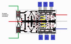
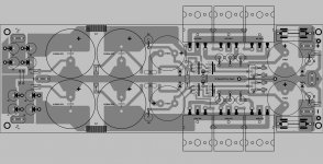
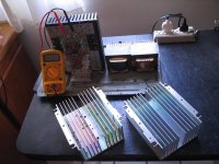
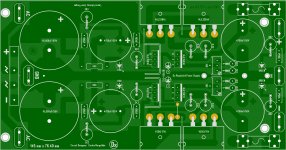
I have prepared the second prototype pcboard
This one a reference to Juan prepare the official pcboard layout.
14 cm by 8.5 centimeters are dimensions.
regards,
Carlos
This one a reference to Juan prepare the official pcboard layout.
14 cm by 8.5 centimeters are dimensions.
regards,
Carlos
Attachments
If the world does not end on December 21, so next year i will release
The Dx DIY Laboratory Supply.
It will have short circuit protection and adjust to almost zero volts.
Here you see the scratch, or sketch, i will develop starting from this circuit.
Of course will be much more sophisticated..this is only the skeleton, the basic topology, the main idea..to be developed by the "Dx Corporation world audiophile union center laboratories from Brazil headquarters"..... ahahahahaha!
but first hold on that idea to destruct the world...people must try to be better to develop the human race...the way it is going, with selfish and envy..no way to have this world the way it is...will be erase and deleted and will start from the beginning once again alike Noah arc.
21 of december, just in case, i will go to the mountains..will do that 20 of December.... just in case as i said....Maya, Jews and Hindu...all them saying things about that date...well.... i will be 2000 meters above the sea level..... just in case.
No lo credo em bruxas, pero que lay hay ... hay!
I do not believe in ghost, but they exist..for sure they exist!
The ones that are reading uncle charlie maybe can do the same...so..we gonna populate the new world.... Dx Corporation will continue to feed the whole world with nice diy circuits.
regards,
Carlos
Attachments

Last edited:
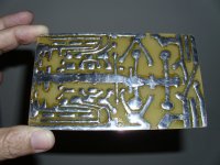
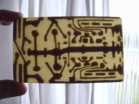
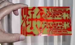
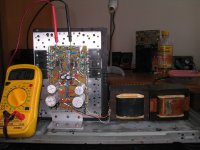
It is looking good..considering was etched at home
and painted using nail polish...hehehhehe.... to result pretty was a miracle!
Dx Power Supply - Prototype assembled. - YouTube
It is only a prototype... Juan is making professional look pcboards....already doing it.
regards,
Carlos
and painted using nail polish...hehehhehe.... to result pretty was a miracle!
Dx Power Supply - Prototype assembled. - YouTube
It is only a prototype... Juan is making professional look pcboards....already doing it.
regards,
Carlos
I have assembled...working great
we can arrange the range of adjustment, also the input voltage...you can use any power transistor into the output, naturally this will depend on your transformer power to select the unit...not only current, but also voltage and dissipation..but it is not critical and almost any transistor will fit.
regards,
Carlos
Attachments
I do think you can..... well... i will make it fit into your needs
Please, inform the maximum current your chip will drain...also if you will use two integrated circuits feeded by a single power supply.... inform the maximum power when distorting and if possible the maximum current and the supply voltage you need.
Inform if you will use 8 ohms, 4 ohms or if you will use some crazy speakers that uses internal passive crossover...also your application.
Will be for home use?
Will be for professional use... as Public Adress or to put sound on parties/games or other events.?
Do your use full power... are you addicted to full power..distorted sounds?... do you plug guitar, bass guitar and synthetizer in your amplifiers?
Sending me these information i will inform you the power transformer to be used and i will match the supply to your needs (if modifications needed)
I know nothing about Integrated Circuits... and i am afraid you will not be able to inform correct data about... datasheet of these things are not that precise...let's say they are too much optimistic.
I have used this supply these last couple of days.... i do think will work fine to you too..it is a very good power supply...here last movies about:
http://www.youtube.com/watch?v=FSzvvO5phWw
http://www.youtube.com/watch?v=mg6hXbYzaD0
http://www.youtube.com/watch?v=KpkSgIuPgzs
regards,
Carlos
Last edited:
Thanks for the reply carlos
It's a 60W by 60W Chip from +-35V, I will use two 8ohm Bookshelves with it, and it's for personal use, No I don't intend to use the full power. My primary amplifier is your DXblame ST") with a -+24V power supply, I love it, best sound ever, this chipamp is just an experiment to make a bi-amped system, I intend to use a 40v40 500VA Transformer for this.
with a -+24V power supply, I love it, best sound ever, this chipamp is just an experiment to make a bi-amped system, I intend to use a 40v40 500VA Transformer for this.
Unrelated---My DXBlame ST


It's a 60W by 60W Chip from +-35V, I will use two 8ohm Bookshelves with it, and it's for personal use, No I don't intend to use the full power. My primary amplifier is your DXblame ST
with a -+24V power supply, I love it, best sound ever, this chipamp is just an experiment to make a bi-amped system, I intend to use a 40v40 500VA Transformer for this.Unrelated---My DXBlame ST
Last edited:
Yes...it will be good for channels operating full power.... to the Blame and also
to your Chip amplifier.
Juan is finishing the layout (some small touches on it), reducing the pcboard size and soon it will be available.
40 volts AC?... this is 56 volts DC... this way using the Blame, adjusted to 35 volts you will have 21 volts into the series pass transistors....full power at 4 ohms you will need 5 amperes to each rail...so... 105 watts dissipation...no problems....supply will do the job laughing, easy and without any worries.
Also to adjust to 30 volts you will have an excellent power supply.
We are working to reduce the board size.... schematic being modified in order to reduce parts count... we are working on that today.... Juan may fix and soon you gonna have layout ready to go.
Go ahead that you will be very happy with it... tested with the Dx Blame amplifiers and worked great!
regards,
Carlos
Attachments
Last edited:
Here you have a test video in english only.
No gusto...i have not measured....but i could see the electronic filtering from the Dx supply almost have killed all noise....i coupled a speaker with a huge condenser and connect the one to the supply output...in the electronic supply input the noise was huge....in the output (loaded) no noise was listened till i touch the speaker into my ear.... there i could see there's a small hum....but really seems to be something that might be 50 db down.
My scope is damaged..no way to make sophisticated measurements.....also i do not know how to make them.
Here you have a video....in English...made today....there's one in portuguese too in my channel:
Dx Symetrical, stablized and adjustable power supply nnnn - YouTube
regards,
Carlos
Last edited:
I have already tested the layout...now making more pcboards
Preparing Dx Supply pcboards at home - YouTube
I am asking Juan to post here the black and white layout for you to etch.
Thank you Zeraphine.
regards,
Carlos
Preparing Dx Supply pcboards at home - YouTube
I am asking Juan to post here the black and white layout for you to etch.
Thank you Zeraphine.
regards,
Carlos
Last edited:
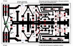
Here are the files need it.
Regards
Juan
Regards
Juan
Attachments
-
Dx Regulated Power Supply cut etching 1.pdf22.6 KB · Views: 672
-
Dx Regulated Power Supply cut etching 2.pdf22.6 KB · Views: 623
-
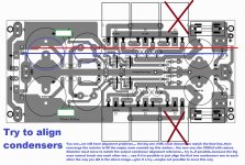
Dx Regulated Power Supply info view.pdf48.8 KB · Views: 775
-
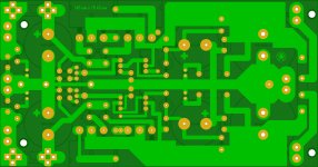 Dx Regulated Power Supply bot.JPG611.2 KB · Views: 959
 -
 Dx Regulated Power Supply top.JPG859.9 KB · Views: 891
- Status
- This old topic is closed. If you want to reopen this topic, contact a moderator using the "Report Post" button.
- Home
- Amplifiers
- Power Supplies
- Dx Supply, output adjustable, stabilized power supply