I do not know.
Não sei quantas onças...ahahahahah!
I do not know how many onces... ahahahahah!
Here you have a complementary video..while doing.
I am still doing, the Dx Supply home boards - YouTube
Picture is onça... this is a brazilian panther
regards,
Carlos
Não sei quantas onças...ahahahahah!
I do not know how many onces... ahahahahah!
Here you have a complementary video..while doing.
I am still doing, the Dx Supply home boards - YouTube
Picture is onça... this is a brazilian panther
regards,
Carlos
Attachments

Last edited:
When you pronunciate ounce, you are speaking the portuguese name for Jaguar
It is onça.... pronouciation is alike ounce.
here you have video part 4... etching.
Dx Supply etching, making of part 3.mp4 - YouTube
regards,
Carlos
It is onça.... pronouciation is alike ounce.
here you have video part 4... etching.
Dx Supply etching, making of part 3.mp4 - YouTube
regards,
Carlos
Something more about power into the Dx Supply
Each case will be studied here:
Dx Supply was made for our friends to save money because electrolitic condensers are very expensive.... It also provides yout stable output voltage and this helps you to achieve the low levels of distortion published.
It was made to receive maximum of 60 plus 60 volts DC and this comes from a 42 plus 42 volts alternated transformer... the maximum power to be drained, under these voltages, is 180 plus 180 watts, and this represents 360 total watts.
So, it was made for you to adjust 42 plus 42 volts into the output...this is the correct voltage to feed the Dx Super A amplifier.
Observe Dx Super A power specifications (42 plus 42 volts), results from the simulator with the supply voltage stable (regulated, stabilized at 42+42)
- 85 Watts RMS at 8 ohms, THD 0.001%, 1.5A plus 1.5A of current drain, that represents a power consumption of 63 watts plus 63 watts (63 watts per rail) and the total of 126W (efficiency is around 67% to 8 ohms).... rail fuses should be slow blow, 1.5A plus 1.5A or a little bit more if you like to enter clipping... speaker series fuse is 3A or a little bit more if you intend to enter clipping.
- 160 Watts RMS at 4 ohms, THD 0.002%, with 3A plus 3A of current drain, that represents a power consumption of 126 + 126W, or total of 254W... rails fuses should be 3A or more, all them slow blow... speaker fuse 6A or more...also slow blow.
- 250 Watts RMS at 2 ohms, THD 0.005%, with 5A + 5A of current drain, that represents a power consumption of 210 + 210W, or a total of 420 Watts of total power consumption.... 5A plus 5A slow blow fuses to the rails and 10A series fuse in series with the speakers (slow blow)
But, if you accept some distortion (we all accept..if we do not accept, the amplifier clips anyway and sometimes we do not perceive so fast it is)...then it can go to:
290 Watts RMS - 2 ohms - 1 percent distortion
330 Watts RMS - 2 ohms - 5 percent distortion
360 Watts RMS - 2 ohms - 10 percent distortion
10% distortion is not that crazy as you think, because some manufacturers (respectable ones) publish integrated circuit distortion at this level of distortion to increase the numbers...watch manufacturer datasheedt about them.
360 Watts RMS is the worst case scenario.... where the supply will face the maximum consumption resulted from the Dx Super A operation at 2 ohms and with 10 percent of distortion... here the current drain goes to 6.3A each rail ... and the consumption is 530 watts to a single channel.
The Dx Supply is good to feed two channels operating simultaneously, at 8 ohms and full power.
The Dx Supply can to feed one channel if you operate at 4 ohms, so, under this sittuation you will need two supplies, one to each channel.
The Dx Supply will need an extra pair of transistors to operate safe if you feed one channel at 2 ohms and drive it to full power (distorted)... you should check your rectifier rating and electrolitic condenser values because the supply was made, mainly, to feed two channels at 8 ohms.... two pair of transistors was the choice to save money into this supply.... so... you gonna need to tweak if you decide to push the limits into 2 ohms loads.... one of the main need is the extra pair of series power transistor...so... as a result, you gonna have three ouput pairs.
The dissipation into these series pass transistors....
... the ones are in the Dx Supply, made to be used together the Dx Super A audio power amplifier.
We gonna have, as the worst case scenario, (when transformer have no voltage... but this is almost impossible....but for safety reasons we take this into our calculations) a voltage drop of 18 volts (60 to 42C) into the series pass transistors, so, multiply this voltage drop by the rail current (that gonna depend your case/choice)... then you will have the power developed into the series pass transistor colector to emitter junctions (input to output of the series pass regulator transistors)
As an example, to clarify the subject, if you have TWO Dx Super A channels, driving 8 ohms loads, operating full power (undistorted), draining energy from a single Dx Supply, will result in 54 plus 54 Watts of power dissipation.... in real world this use to be much less, because we have voltage drop into the Dx Supply input, so, voltage drop from colector to emitter being reduces will reduce the result of the multiplication of current by the voltage that results in the power.
regards,
Carlos
I am busy at work and at my job.
I could not assemble the Dx Supply to test the pcboard layout
Dx Supply part 3 - I am busy both at home and job - YouTube
regards,
Carlos
I could not assemble the Dx Supply to test the pcboard layout
Dx Supply part 3 - I am busy both at home and job - YouTube
regards,
Carlos
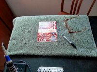
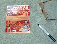
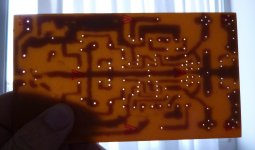
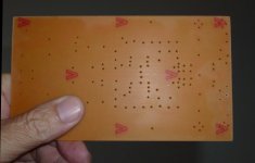
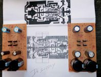
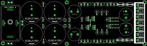
I am assembling the Dx Supply using home etched pcboards
Resulted not that good (etching process no good) but i am fixing errors and assembling anyway.
I am waiting new condensers that gonna arrive from USA, a gift from Evette/Dudainc..... a box with 40 units of 4700uf/63 volts will arrive and will substitute the temporary ones i am using (old ones and smaller ones)
This is being made to be used together the Dx Super A triple, one channel for bass having a low pass filter and two channels without any input filtering...just potenciometer in the input...all clear of troubles and pre amplifiers that can mess with the audio reproduction.
Here you have a picture...i am doing it slowly, as i am waiting for new pcboards from the Dx Super A, transistors from Evette (Canadá) and pcboards from Juan Vargas (Puerto Rico)
Here you have Dx Super A thread:
http://www.diyaudio.com/forums/solid-state/221741-dx-blame-st-together-dx-super.html
regards,
Carlos
Attachments
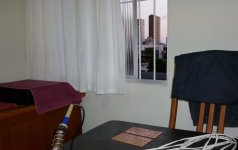
I am using one of these two supplies you see in the last post
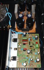
I am trying the Dx Supply once again, this time i have installed 25.000 plus 25.000uf, the amplifier is operating with 38 Volts, the supply voltage unloaded is 44 volts...loading it drops to 40 volts and keeps the output voltage stable...highly filtered as i tortured with 1 hertz and no noise from the supply, totally and absolutelly silent even when we drain high currents.
Speaker is using 4 ohms coil (it is dual coil) and i have pushed almost 100 watts RMS... due to 6 volts of voltage drop into the series pass transistors (from colector to emitter) i am having some heat into my test small heatsinks.... but when draining high current the voltage drop into series pass transistor is only 2.3 volts...this way heat is not that big.
Circuit is Dx Super A operating with one single pair in the output and i cannot push it hard because of that.... 100 watts only a few seconds.
As you can see, i have simplified the supply to enjoy it's power while i am waiting more transistors, pcboards and electrolitic condensers.
Just to be listening the Dx Super A and to have fun.
regards,
Carlos
Attachments
We have found a mistake, a bypass capacitor not connected to ground
Because of that Juan has fixed the layout.
Here you have them.
regards,
Carlos
Because of that Juan has fixed the layout.
Here you have them.
regards,
Carlos
Attachments
DX Super A Ragulated PSU
Uncle Charlie,
According to the set of condensers and power transistors are they capable enough to drive DX Super A stereo in 2 Ohms load?
If not what would be the required changes? to obtain 1 Regulated PSU to drive stereo in 2 ohms load?
Regards,
Uncle Charlie,
According to the set of condensers and power transistors are they capable enough to drive DX Super A stereo in 2 Ohms load?
If not what would be the required changes? to obtain 1 Regulated PSU to drive stereo in 2 ohms load?
Regards,
Attachments
Uncle Carlos,
Are those vertically mounted resistors of 2watter rating?..and what is the rating of BZV55-C12 zener, I have been consulting datasheets but it seems it was of SMD type.
Thank You!
@willjj78
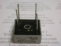
Holeee...your diode is huge man!
Nice lay-out!, do you happen to have a lay-out for MB5010W type of bridge diode? Those inline pin type of bridge diode in PH comes in low amperes.
Regards!
MB5010W datasheet(1/2 Pages) MCC | 50 Amp Single Phase Bridge Rectifier 50 to 1000 Volts
Are those vertically mounted resistors of 2watter rating?..and what is the rating of BZV55-C12 zener, I have been consulting datasheets but it seems it was of SMD type.
Thank You!
@willjj78
Holeee...your diode is huge man!
Nice lay-out!, do you happen to have a lay-out for MB5010W type of bridge diode? Those inline pin type of bridge diode in PH comes in low amperes.
Regards!
MB5010W datasheet(1/2 Pages) MCC | 50 Amp Single Phase Bridge Rectifier 50 to 1000 Volts
Attachments
@willjj78
Holeee...your diode is huge man!
Nice lay-out!, do you happen to have a lay-out for MB5010W type of bridge diode? Those inline pin type of bridge diode in PH comes in low amperes.
Regards!
MB5010W datasheet(1/2 Pages) MCC | 50 Amp Single Phase Bridge Rectifier 50 to 1000 Volts[/QUOTE]
...Why not? just waiting Uncle charlie's confirmation about few questions so i can finalize, stay tuned....
Regards,
Wiljj78
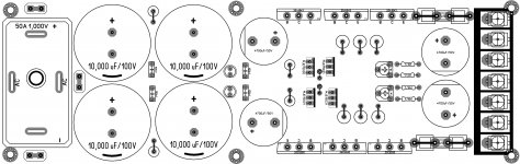
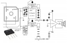
Hey dear Willy I really don't want to to change you idea of using those large bridge rectifiers but if you are happy with that is just fine be happy, but I guess is not that necessary to use so large unit you can use smaller unit too save money, this is how I see Dx Regulator the bridge rectifier you see in this illustration just cost 2 dollar and some change, remember Dx Regulator is a like a water tank and some valves that control the fluids, so the rectifier is just a big lake or river is just provide the water and the valves control the fluids, that is the way I see it, the capacitor act as a large reservoir thank, and the Dx Regulator act as a valve control unit and also filters the impurities from the mains of the lake like rocks sand dirt, sorry this might be to confuse but is the way I see it I hope you like my thinking dear Willy.
Regards
Juan
Regards
Juan
Attachments
Last edited:
Hey dear Willy I really don't want to to change you idea of using those large bridge rectifiers but if you are happy with that is just fine be happy, but I guess is not that necessary to use so large unit you can use smaller unit too save money, this is how I see Dx Regulator the bridge rectifier you see in this illustration just cost 2 dollar and some change, remember Dx Regulator is a like a water tank and some valves that control the fluids, so the rectifier is just a big lake or river is just provide the water and the valves control the fluids, that is the way I see it, the capacitor act as a large reservoir thank, and the Dx Regulator act as a valve control unit and also filters the impurities from the mains of the lake like rocks sand dirt, sorry this might be to confuse but is the way I see it I hope you like my thinking dear Willy.
Regards
Juan
Hello Dear Jaun,
Completely agree the way your thingking my dear, but you know my way of building my projects i always use junk/recycled parts rather than buying
....thats why i always customize my build in order to use my parts on stock, i think that's the way i can save money rather than buying new parts... If you notice i have asked uncle charlie if this design would be capable to drive stereo in 2 ohms load that means i wish/need only to have 1 stabilizer pcboard rather than 2 PSU pcboard for stereo DX Super A (if possible), and thats the entire idea why i increase the rectifier. Regards,
Wiljj78
Last edited:
ahaaaaa now I see, good dear Willy just great so you actually build according to your parts, I like that my man I like that very good! yes Carlos post all that info in post #420 Carlos has it all 9 yards cover already dear Willy
It can put out more or less 70 watts at low distortion... can go more, with reasonable distortion, can reach 90 watts RMS at 8 ohms.... in this case you have the need of 150 to 180 watts (VA) transformer to 1 channel.... to each channel .... if you decide to use a single transformer and a single supply to feed two channels, then you must have a 300 to 360 watts (VA) power transformer..depending if you adjust your volume lower than the threshold of distortion or higher than the threshold of distortion....this depends on the music you play and the volume you like to play and how sensitive are your ears to clipping and harmonic distortion....
Transformers are 30 plus 30 volts AC, because after rectification and filtering you gonna have a resultant DC voltage of 42 plus 42 volts.
So, first answer goes to 8 ohms.....transformer should be 150 watts(VA) each if you intend to buy two transformers........or 300 watts (VA) to feed two channels using a single transformer.
So, second answer goes to 4 ohms speakers.... transfomer should be twice the above current.... 300 watts each one of two transformers if you intend to buy two transformers and to make two separated supplies, each one of them to feed one channel...or 600 watts (VA) single transformer if you intend to use a single power supply.
So, third answer goes to 2 ohms speakers.... transformer should be twice the above current, or 600 Watts (VA) each one of two transformers if you intend to buy two transformers and to make two separated supplies (transformer, plus rectifiers plus filters).... but if you decide to use a single power transformer to feed two channels..then the choice will be 1200 watts power transformer.
This amplifier can put out aproximatelly 70 watts at 8 ohms each channel, 150 watts at 4 ohms to each channel and can reach 320 watts rms to each channel at 2 ohms loads.
Fuses to the positive and negative rails should be:
8 ohms speakers = 1.5A plus 1.5A...these goes into the audio amplifier pcboard...output series fuse can be 3 to 3.5 amperes..slow blow fuses.
4 ohms speakers = 3A plus 3A ... these ones goes into the audio amplifier pcboard .... output series fuse to the speaker can be 6 amperes.
2 ohms speakers = 6A plus 6A ... these ones goes into the audio amplifier pcboard.. output series fuse to the speaker can be 12 amperes.
Electrolitic condensers for filtering you calculate... use 5000uf to each ampere...so....if your supply will power a single pcboard at 8 ohms...then it is 1.5 plus 1.5 amperes..then put 7500uf plus 7500uf or more as filters...rectifiers should be twice this power.
You see that for 2 ohms you gonna need 30 thousand microfarads to each rail...so... 30K plus 30K...and this to a single power amplifier..reason why i suggest you to use a series pass regulator that has capacitance multiplier effect or search for something alike Dx Power Supply..... you can find it at the Power Supply forum.... for sure others may fit, the electronic filtering reduces the ammount of capacitance from several electrolitics....this is too much expensive when you drain high current.
Primary fuses you divide the power of your transformer expressed in watts by your mains voltage...then you have the fuse, use the value or the immediate superior value found in the market.
Heatsinks:
To each 10 watts of audio power ( the maximum power you gonna reach depends your transformer power and depends on your speaker impedance) then use an aluminum blade of 10 by 10 centimeters (4 inches by 4 inches..so..squared)...this is the equivalent size to 10 watts of AUDIO power... so.... depending your power you can evaluate your heatsink...use fan blower anyway... this heatsink dimension (tested in laboratory, under 30 degrées centigrades environment being able to face a 10 watts RMS audio amplifier, operating class AB or class B, having sinusoidal signal in the output, undistorted or unclipped waveform)
This is to continuous.... music is average.... this results twice the needed size for music...so...you can calculate.
But Class A and Super A operation is different..generates too much heat and these calculation does not make any sense.... reason why i suggest to install fan blower having LM7808 or even LM7805 or other manufacturer, voltage regulator integrated circuits to power the fan, reducing voltage will reduce fan speed and fan noise....but be attention, these Voltage Regulator Chips have a limit of input voltage you should see in the datasheet.
regards,
Carlos
Regards
Juan
yes Carlos post all that info in post #420 Carlos has it all 9 yards cover already dear Willy It can put out more or less 70 watts at low distortion... can go more, with reasonable distortion, can reach 90 watts RMS at 8 ohms.... in this case you have the need of 150 to 180 watts (VA) transformer to 1 channel.... to each channel .... if you decide to use a single transformer and a single supply to feed two channels, then you must have a 300 to 360 watts (VA) power transformer..depending if you adjust your volume lower than the threshold of distortion or higher than the threshold of distortion....this depends on the music you play and the volume you like to play and how sensitive are your ears to clipping and harmonic distortion....
Transformers are 30 plus 30 volts AC, because after rectification and filtering you gonna have a resultant DC voltage of 42 plus 42 volts.
So, first answer goes to 8 ohms.....transformer should be 150 watts(VA) each if you intend to buy two transformers........or 300 watts (VA) to feed two channels using a single transformer.
So, second answer goes to 4 ohms speakers.... transfomer should be twice the above current.... 300 watts each one of two transformers if you intend to buy two transformers and to make two separated supplies, each one of them to feed one channel...or 600 watts (VA) single transformer if you intend to use a single power supply.
So, third answer goes to 2 ohms speakers.... transformer should be twice the above current, or 600 Watts (VA) each one of two transformers if you intend to buy two transformers and to make two separated supplies (transformer, plus rectifiers plus filters).... but if you decide to use a single power transformer to feed two channels..then the choice will be 1200 watts power transformer.
This amplifier can put out aproximatelly 70 watts at 8 ohms each channel, 150 watts at 4 ohms to each channel and can reach 320 watts rms to each channel at 2 ohms loads.
Fuses to the positive and negative rails should be:
8 ohms speakers = 1.5A plus 1.5A...these goes into the audio amplifier pcboard...output series fuse can be 3 to 3.5 amperes..slow blow fuses.
4 ohms speakers = 3A plus 3A ... these ones goes into the audio amplifier pcboard .... output series fuse to the speaker can be 6 amperes.
2 ohms speakers = 6A plus 6A ... these ones goes into the audio amplifier pcboard.. output series fuse to the speaker can be 12 amperes.
Electrolitic condensers for filtering you calculate... use 5000uf to each ampere...so....if your supply will power a single pcboard at 8 ohms...then it is 1.5 plus 1.5 amperes..then put 7500uf plus 7500uf or more as filters...rectifiers should be twice this power.
You see that for 2 ohms you gonna need 30 thousand microfarads to each rail...so... 30K plus 30K...and this to a single power amplifier..reason why i suggest you to use a series pass regulator that has capacitance multiplier effect or search for something alike Dx Power Supply..... you can find it at the Power Supply forum.... for sure others may fit, the electronic filtering reduces the ammount of capacitance from several electrolitics....this is too much expensive when you drain high current.
Primary fuses you divide the power of your transformer expressed in watts by your mains voltage...then you have the fuse, use the value or the immediate superior value found in the market.
Heatsinks:
To each 10 watts of audio power ( the maximum power you gonna reach depends your transformer power and depends on your speaker impedance) then use an aluminum blade of 10 by 10 centimeters (4 inches by 4 inches..so..squared)...this is the equivalent size to 10 watts of AUDIO power... so.... depending your power you can evaluate your heatsink...use fan blower anyway... this heatsink dimension (tested in laboratory, under 30 degrées centigrades environment being able to face a 10 watts RMS audio amplifier, operating class AB or class B, having sinusoidal signal in the output, undistorted or unclipped waveform)
This is to continuous.... music is average.... this results twice the needed size for music...so...you can calculate.
But Class A and Super A operation is different..generates too much heat and these calculation does not make any sense.... reason why i suggest to install fan blower having LM7808 or even LM7805 or other manufacturer, voltage regulator integrated circuits to power the fan, reducing voltage will reduce fan speed and fan noise....but be attention, these Voltage Regulator Chips have a limit of input voltage you should see in the datasheet.
regards,
Carlos
Regards
Juan
Last edited:
The whole 9 yards
The whole nine yards
From Wikipedia, the free encyclopedia
Jump to: navigation, search
This article is about the phrase. For the film, see The Whole Nine Yards (film).
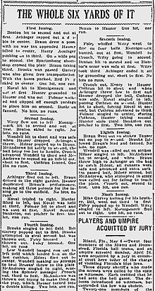
A 1921 headline from The Spartanburg Herald-Journal in South Carolina reads "The Whole Six Yards of It." In 1956, the expression was used in a magazine for Kentucky outdoorsmen with the number of yards given as nine. This type of upward revision has been described as "phrase inflation."[1]
The whole nine yards is a phrase used to indicate “the full extent”, or “the whole thing,” as in, They took my wallet, my keys, my shoes, – the whole nine yards! Its origin is unknown and has been described as, "the most prominent etymological riddle of our time."[2]
The earliest recorded example of this phrase dates from 1956.[1][3] It is related to the expression "the whole six yards," used earlier in the rural South. Both phrases are variations on the whole ball of wax, first recorded in the 1880s.[4] They are part of a family of expressions in which an odd-sounding item, such as enchillada, shooting match, or shebang, is substituted for "ball of wax."[4] The choice of the number nine may be related the expression "to the nines" (to perfection).[nb 1]
The phrase was introduced to a national audience by Elaine Shepard in the Vietnam War novel The Doom Pussy (1967).[5] Use of the phrase became widespread in the 1980s and 1990s. Much of the interest in the phrase's etymology can be attributed to New York Times language columnist William Safire, who wrote extensively on this question.
The whole nine yards - Wikipedia, the free encyclopedia
Regards
Juan
The whole nine yards
From Wikipedia, the free encyclopedia
Jump to: navigation, search
This article is about the phrase. For the film, see The Whole Nine Yards (film).

An externally hosted image should be here but it was not working when we last tested it.
A 1921 headline from The Spartanburg Herald-Journal in South Carolina reads "The Whole Six Yards of It." In 1956, the expression was used in a magazine for Kentucky outdoorsmen with the number of yards given as nine. This type of upward revision has been described as "phrase inflation."[1]
The whole nine yards is a phrase used to indicate “the full extent”, or “the whole thing,” as in, They took my wallet, my keys, my shoes, – the whole nine yards! Its origin is unknown and has been described as, "the most prominent etymological riddle of our time."[2]
The earliest recorded example of this phrase dates from 1956.[1][3] It is related to the expression "the whole six yards," used earlier in the rural South. Both phrases are variations on the whole ball of wax, first recorded in the 1880s.[4] They are part of a family of expressions in which an odd-sounding item, such as enchillada, shooting match, or shebang, is substituted for "ball of wax."[4] The choice of the number nine may be related the expression "to the nines" (to perfection).[nb 1]
The phrase was introduced to a national audience by Elaine Shepard in the Vietnam War novel The Doom Pussy (1967).[5] Use of the phrase became widespread in the 1980s and 1990s. Much of the interest in the phrase's etymology can be attributed to New York Times language columnist William Safire, who wrote extensively on this question.
The whole nine yards - Wikipedia, the free encyclopedia
Regards
Juan
Thank you very much my dear Juan,
All informations above was descrived about the required power for Super A includes per channel, transformer capabilty in terms of load and filters, but i need to know about filters vs. power transistor qty. to match/meet the requirements of stereo in 2 ohms load for this particular stabilizer only.
Regards,
Wiljj78
Last edited:
oh wow but Willy Dx Super A is not to keep it at high volume levels and small loads 2 ohms load,
all the time is a fine designed amplifier for enjoyably experiences, what exactly are you looking for dear Willy power or high fidelity? I'm completely honest Dx Super A has it all, not need to look around for more stuff, but well wait for Carlos he design the Dx Regulator he probably got and answer for you.
Regards
Juan
- Status
- This old topic is closed. If you want to reopen this topic, contact a moderator using the "Report Post" button.
- Home
- Amplifiers
- Power Supplies
- Dx Supply, output adjustable, stabilized power supply