I have asked this question in several forums now with no response, and have searched but not found an answer. So I am posting this as a new thread.
Can one connect multiple switch mode power supply (SMPS) bricks from laptops for example, to boost the amps rating? I have lots of 19 volt 4.6 amp (90W) bricks lying around, and if need more, they cost $9 ea to buy. Maybe use blocking diodes and a fat capacitor at common supply point to smooth out? What are the problems or issues with this?
I want to tie maybe 4 of them together to power a class D amp.
Thanks in advance.
Xrk971
It isn't recommended to parallel two or more of them if they hasn't a "share" or similar circuit to make both (Or more) PS give the same voltage AND current at the same time.
For example, let one of them to have, say, 12V and another 12.1V, making gross number to see the difference. When paralleling, the 12.1V will be idle. You can use diodes or ballast resistors, but it will degrade the supply performance as voltage sense will be done before this resistors.
For example, let one of them to have, say, 12V and another 12.1V, making gross number to see the difference. When paralleling, the 12.1V will be idle. You can use diodes or ballast resistors, but it will degrade the supply performance as voltage sense will be done before this resistors.
Ok, does not recommended mean it won't work? I know you can't do this with linear supplies without having a master supply driving slave pass transistors. For switchers, their internal sense tries to maintain the constant voltage. If the voltage sags on one power supply and it can't keep up, would not the common tie point voltage drop and hence force all power supplies to do their thing to keep up? Maybe I am being too simple minded but I am thinking about as a reservoir with the big capacitor and each supply does its job to refill this cap to maintain voltage. I agree that the voltage needs to be close, but maybe what you are saying that is even if the voltage is off by tiny amount, the power supply will not switch on to refill The capacitor?
Returning to my previous example, if you wire them in parallel directly, and if both of them has (as must have) a big open loop gain in their error amplifier, then the higher voltage supply will be driven by the lower to a so small duty cycle that it may be full shut down. Or if not, the higher voltage SMPS will carry the other behind the duty cycle limit (For example in a forward converter in which max duty is <50% by definition), and to destroy or go overvoltage shutdown. The cap you suggest, I believe is useless, because for DC it is open circuit. It can help in transients only.
I believe you have certain technical knowledge, why not to try to make a kind of master/slave configuration in similar way as linear counterparts?
I use it in a 180 deg out of phase solar cells switching regulator and performs fine.
I believe you have certain technical knowledge, why not to try to make a kind of master/slave configuration in similar way as linear counterparts?
I use it in a 180 deg out of phase solar cells switching regulator and performs fine.
Last edited:
I would rather build speakers and buy power supplies. I used To build my own linear supplies all time in my younger days, but have no experience with switchers. Maybe hack into a laptop brick and intercept the voltage sense and connect it to common point? Use switching drive voltage from one master to all slave mosfets. It might be fun, but alas, I barely have enough time to make speakers.... ") thanks for your input though. Does anyone have any ideas on how to make cheap higher current supplies for Class D amps?
thanks for your input though. Does anyone have any ideas on how to make cheap higher current supplies for Class D amps?
thanks for your input though. Does anyone have any ideas on how to make cheap higher current supplies for Class D amps?I have done the parallel trick with 2 SMPS when desperate but only for short testing purposes. What you ideally want are outputs that sag a little on load, say 50mv, but have voltages at the same load within say 10mv. So, you might have to hand select supplies or find a way to adjust the feedback. One way if there are sense wires is to add a little resistance or miniscule ratio potential divider in the sense lead. The sagging could be realised with a series output resistor in each output, as I say 50mv is enough to get reasonable sharing. You don't want supplies that latch off in overcurrent, then at the limit they'll share anyway because as one shuts down its voltage falls and the other one becomes the main source and wants to deliver all the current but then that will shutdown etc etc.
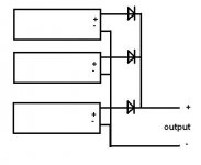
Diode isolation will help distribute load sharing without having any one supply pump current into another.
Equal (same V & I output) supplies recommended.
Use schottkey diodes at 5 to 10 times rated current load for less drop.
Dug,
Thank you! I suspected that it might work, and I do have identical bricks to try this with. I hope those Schottky diodes aren't too pricey
Can one connect multiple switch mode power supply (SMPS) bricks from laptops for example, to boost the amps rating? I have lots of 19 volt 4.6 amp (90W) bricks lying around, and if need more, they cost $9 ea to buy. Maybe use blocking diodes and a fat capacitor at common supply point to smooth out? What are the problems or issues with this?
I want to tie maybe 4 of them together to power a class D amp.
Xrk971
I suspect that you need more than 19 volts for your amp.
So, are we talking about series connecting 4 bricks for +/-38 volts center tapped ?
If so then no paralleling, no problem ...
well, I thought 19 volts is a little low for an amp which needs 20 amps ...
unless the amp has a built-in upconverter of course.
this is what I did some time ago running two in parallel:
check that the output voltages for - say - 1 amp load are within - say - 0.25volts
then put a small resistor to each + output and tie them together
0.1 ohm should do the job dissipating 2.5watts though at 5 amps
but unless you run sine-wave tests at full output the average power loss will be much lower
Last edited:
I wasn't going to series them with center tap but that is not an option? Why?
I don't see why not. It might take up a bit of space but I'm all for designing around what you have.
I wish I had a stack of those 19V smps.
I only have one (19.5V @ 4.95A) and it is enough to run my 2 ch BTL 8R class D for (I calculate roughly) 21W / ch
But I would need another to run the sub at 4R.
Diode isolation will help distribute load sharing without having any one supply pump current into another.
Equal (same V & I output) supplies recommended.
Use schottkey diodes at 5 to 10 times rated current load for less drop.
There's already output diodes inside each PS, so they weren't needed in my parallel example, or probably any other typical PS - perhaps not synchronous rectifiers though. There won't be any current fed from one to the other.
Series could be different though, some rectifiers may not handle the extra voltage across one diode at switch off if powering a capacitive load and the 2 PSs own capacitors aren't matched.
Yes there could be problems if they were different..I thought they were the same.
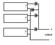
I thought of another issue with putting them in series that would require adding a protection diode...see jpg
Attachments
if they are IDENTICAL i think you should have no problems running them as long as they always have atleast a small load on them. i run 4 computer psus in parallel and have no problems. 12v at 80amps lol
This exactly the type of info I wad looking for. Someone who actually has done it. Are you doing anything special like blocking diodes, resistors to provide load matching etc or just tie 4 in parallel? And is it really delivering a measured 80 amps or close with load sucking away at the power?
I don't see why not. It might take up a bit of space but I'm all for designing around what you have.
I wish I had a stack of those 19V smps.
I only have one (19.5V @ 4.95A) and it is enough to run my 2 ch BTL 8R class D for (I calculate roughly) 21W / ch
But I would need another to run the sub at 4R.
They are cheap enough to buy circa $8 ea, I feel less Expensive than equivalent single smps, Aand I don't think they are bigger than comparable supply at same load rating. The bricks are 2 x 1 x 5 inches each or 10 cubic inches for 90 watts. Or 360 watts for 40 cubic inches.
well, I thought 19 volts is a little low for an amp which needs 20 amps ...
unless the amp has a built-in upconverter of course.
this is what I did some time ago running two in parallel:
check that the output voltages for - say - 1 amp load are within - say - 0.25volts
then put a small resistor to each + output and tie them together
0.1 ohm should do the job dissipating 2.5watts though at 5 amps
but unless you run sine-wave tests at full output the average power loss will be much lower
Why is a resistor needed? To provide slight load and voltage drop?
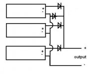
Dug, can you show which wires are connected? The dwg crosses.
Sorry, should have made it clearer.
Negatives all together, positives together after diodes, reverse diode protection added.
Attachments
- Status
- This old topic is closed. If you want to reopen this topic, contact a moderator using the "Report Post" button.
- Home
- Amplifiers
- Power Supplies
- Laptop SMPS Bricks in Parallel?