Oh! that sounds a lot more optimistic!
This is from from the PS-3 instructions (attachment)
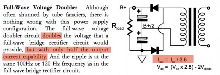
So according to that formula on the right, I take the required amp draw number from the signal heaters (apparently 2.5Amps) and divide it by 3.5 to get the result? 0.7amps through transformer?
Boy I hope I squeeze through this pinch...
This is from from the PS-3 instructions (attachment)
So according to that formula on the right, I take the required amp draw number from the signal heaters (apparently 2.5Amps) and divide it by 3.5 to get the result? 0.7amps through transformer?
Boy I hope I squeeze through this pinch...
Attachments
The AC fluxes of primary and secondary are almost exactly balanced, but the DC part remains completely unbalanced and simply results in the magnetization of the core. In an air cored transformer, this would be completely undetectable from the primary side: just like having a permanent magnet in the vicinity.The DC does not "go through" the transformer; it goes separately, but relatedly, through the primary and secondary. The flux generated by the primary current is almost exactly balanced by the flux generated by the secondary current.
With a high permeability core not designed to work as a choke, this will shift the magnetization curve and result in asymmetrical saturation.
Anyway, one thing is for sure: no DC will be drawn from the mains. That would hold true even with the secondary directly shorted with a diode.
Ok... Some more info:
The phonodude features 4 tubes total.
The signal heaters feature 2 5755 Tubes and 2 ECC83C tubes. The Amps in parallel of the 5755 tube is 360mA and the the ECC83C in parallel is 300mA.
What would be the total amperage of the circuit? I have a funny feeling its not 2 to 2.5 amps? Is this right?
-edit
I ask this because if all these tubes filaments are wired in parallel, the amperage should be around 300mA? not 2 some Amps? because half an amp is much nicer than 2 or whatever the ps-3 is suggesting.
Last edited:
Elvee:
If you are right, then it would not be possible to use an isolation transformer to run an AC/DC radio (with half-wave rectification). Vintage wireless enthusiasts do this all the time; I have not heard of any complaints about transformer buzzing.
Two 5755 in parallel would be 720mA, two ECC83 would be 600mA so a total of 1.32A at 6.3V. Where does your 2.5A figure come from?
A major relief! I got that number from the tubecad's PS-3 power supply manual. For some goofy reason, and I look back on it now, I have no idea why it said "12-12.6Vac @ 2.5A for 12Vdc or 12.6Vdc (FW -Bridge)". I'm not sure why it was specified to be @2.5. It just seemed highly noteworthy if he included it in the wiring instructions
Now I feel relieved...
Now I feel relieved...
I never implied that it was impossible to use half wave rectification on a transformer, simply that it had serious inconvenients and is therefore bad practice, and that it would not offset the primary current.Elvee:
If you are right, then it would not be possible to use an isolation transformer to run an AC/DC radio (with half-wave rectification). Vintage wireless enthusiasts do this all the time; I have not heard of any complaints about transformer buzzing.
As for the buzzing, it is highly dependent on the transformer: some won't tolerate the slightest hint of polarization, others will happily accept huge imbalance.
It has to do with the core (EI vs toroidal, etc), the type of iron (magnetostrictive or not), the construction (quality of impregnation) and other factors.
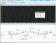
Here is an illustration of the situation: a 1:1 isolation transformer of ~200VA is connected to a resistive load, either directly, or via a diode.
The transformer has its iron core simulated with reasonable accuracy.
Note that there are not even filter caps in circuits.
The first pic shows the plain resistive load: the current drawn is almost sinusoidal and the rms value is 874mA. No surprise there.
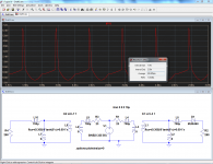
Next is the primary current with a half wave rectified load: the rms current is now 1.47A, almost doubled for an effective load halved!
This means a transformer used in this way has to be severely derated. In addition, the iron losses are also increased, but it is not possible to compute the core losses with LTspice.
Also, the primary waveform is severely distorted, and this could send perturbations elsewhere in the circuit.
This is a simulation of course, but real oscillograms are very similar.
Maybe Simon7000 could provide some actual examples, he seems to have recorded such waveforms?
Attachments
The issue seems to have changed from DC to a spike waveform. The size of the spikes will depend to some extent on stray capacitance. I'm not sure to what extent this is included in your model.
I accept that half-wave rectification will mean a derating of the transformer. However, we are only talking in this thread about one secondary so the net effect will be small.
I accept that half-wave rectification will mean a derating of the transformer. However, we are only talking in this thread about one secondary so the net effect will be small.
old hat now, but post61 showed a formula where
Iout = Iac / 3.6
This can be re-arranged to:
Iac = Iout * 3.6 (when you move a term from one side to the other you change it's operator, divide > multiply, or multiply > divide, or add > subtract, or subtract > add).
and if you need
VA = Iac * Vac
If you build a doubler, or tripler, you will find that the voltage droop when delivering full load current is high.
this is because the resistance before the smoothing has a very large effect on the output voltage.
I think for a doubler the voltage loss is double what a single would be at the same current. A tripler is even worse.
The issue has always been about a distorted primary waveform, not DC.The issue seems to have changed from DC to a spike waveform. The size of the spikes will depend to some extent on stray capacitance. I'm not sure to what extent this is included in your model.
No stray capacitance is included in the model, because for 50Hz the effect of even ten's of nF on currents of amperes is infinitesimal.
The spikes are caused only by the magnetization trying to pull the curves towards one polarity and crashing into the saturation limit of the core, very much like the diode of a DC restorer has to provide high and short peaks of current to compensate for a bias current.
In this case, the secondary voltage is 12V rms, and the peak asymmetrical current reaches 6.5A, that is in excess of 110VA peak.I accept that half-wave rectification will mean a derating of the transformer. However, we are only talking in this thread about one secondary so the net effect will be small.
The transformer would need to be very big to make this negligible, given the disproportionate effect of such an asymmetry on the whole transformer.
Not a fair comparison. If you push a transformer well away from its nominal resistive load spec you need to derate it. You have not derated enough.
DC was your original point. You have now shifted the goalposts.
Note that in order to get the rectifier heating right the RMS current must be 1.9A. This means that the secondary heating due to ohmic losses will be exactly the same.
DC was your original point. You have now shifted the goalposts.
Note that in order to get the rectifier heating right the RMS current must be 1.9A. This means that the secondary heating due to ohmic losses will be exactly the same.
The point of the sim was precisely to make a fair comparison: everything identical, except there is a diode in series with the load meaning the transformer only delivers 100W instead of 200W.
In spite of the reduction, the rms input current almost doubles. We could scale the currents by 50%, the relative gap would remain the same.
If another identical secondary is added with a diode in the opposite direction, everything would be normalized, rms current, waveform, etc. Yet it is twice the non-linear load.
And at no time will there be a DC component in the primary current: this can be seen from the average current in the sim (the few µA's are caused by rounding and sampling errors).
Anyway I give up there: for me, everything that needed to be said has been said
- Status
- This old topic is closed. If you want to reopen this topic, contact a moderator using the "Report Post" button.
- Home
- Amplifiers
- Power Supplies
- 12 to 5 AC Rectification