Maybe.
The filament doesn't mind the "spiky" supply because of its huge thermal inertia. (In CRT TV's it's common to run a 6.3 volt heater with from a high frequency pulse of around 22 volts peak).
Are we stressing the transformer too much though. More current over only half a cycle.
Just ideas")
The filament doesn't mind the "spiky" supply because of its huge thermal inertia. (In CRT TV's it's common to run a 6.3 volt heater with from a high frequency pulse of around 22 volts peak).
Are we stressing the transformer too much though. More current over only half a cycle.
Just ideas
Attachments
It is inded a waste, but it is simple and safe if you dimension the resistor(s) properly.Step down 7 volts using power resistors? That doesn't seem like a lot of energy waste to me... But this theoretically should work right? If I know that the tube rectifier filiment runs at 1.9A, I can put a resistor that stops down the voltage to be at 5V upon load. No capacitor hassle. Can someone verify if I can make that jump safely? (12V to 5v using only resistors)
That would be an abomination: it would magnetize the transformer, and it would buzz like mad.Also another idea came to mind:
What If I constructed a half wave rectifier to get half the voltage and try to smooth it out with a capacitor. And then deal with the remainder few volts by resistors.
Or am I wasting time trying to deal with diodes. Any harm to the transformer doing half waves?
If you smooth with a capacitor, it would be worst: the peak rectified output of a half wave rectifier is the same as for a full wave, it would simply create more stress on the components, the capacitor in particular.
Half wave could be a solution if you can balance it somewhere else with an opposite VA half wave.
The only realistic options for a wattless dropper are:
a) Conduction angle control (but it wil send harmonics all over the the place)
b) Inductive dropping. It can be made to work, but the reactor will have ~the size of a 12~14VA transformer, and it has to be carefully calculated (the air gap in particular)
I think your tester only works at 1KHz. The picture at 50Hz is quite different.
http://www.diyaudio.com/forums/parts/131339-me-my-tan-theta-meter-capacitor-tester.html
Everything can always be made to work, but this doesn't mean it is a good idea.I still think this could be made to work. In a hazy blur this was partly one reason why I kept the series trim resistor, to "lighten the work" the caps do.
Stacking two dozens of caps is a possibility, but not a very attractive one.
The leakage inductance of the transformer will make things slightly worse, because part of the capacitive VAR you install will have to compensate for it before any dropping can occur.My concern last night was trying to visualise the reactive load in combination with the inductive transformer winding. The voltage source in LTspice isn't inductive. I concluded that wasn't an issue in practice with the "real" resistive load.
Mixing reactive and resistive dropping is not very effective either, because the two vectors are in quadrature
Actually, if you accept some complexity, there are other options.The only realistic options for a wattless dropper are:
a) Conduction angle control (but it wil send harmonics all over the the place)
b) Inductive dropping. It can be made to work, but the reactor will have ~the size of a 12~14VA transformer, and it has to be carefully calculated (the air gap in particular)
The most obvious one being an SMPS 16V-->5V, but there are also cleverer possibilities, like voltage dividers AC or DC.
Actually, if you accept some complexity, there are other options.................
Of course... but complexity is the problem.
As I type this I have a 30Vac transformer feeding a 20 year old 270uf/400v cap in series with a 5 ohm 50 watt resistor bolted to a heatsink (the resistor not the cap
). All is well and the resistor has around 10 volts AC across it (measured). So we're pulling around 2 amps. The cap must have a ripple current rating of no more than 300ma or so. I would guess after 20 minutes that it has gone to about 10 degrees C above ambient.
I think with suitable choice of cap this idea would be OK.
Some more "on the fly thoughts". If caps were paralled then maybe include a small resistor in series with each one. Hazy thoughts again... differing E.S.R. values with identical caps and all that...
There are plenty of caps with ripple current ratings over 3 amp.
Worth investigating I would say.
More like 3A probablyAs I type this I have a 30Vac transformer feeding a 20 year old 270uf/400v cap in series with a 5 ohm 50 watt resistor bolted to a heatsink (the resistor not the cap
All is well and the resistor has around 10 volts AC across it (measured). So we're pulling around 2 amps. The cap must have a ripple current rating of no more than 300ma or so.
Drawing general conclusions from anecdotal evidence can be risky.I would guess after 20 minutes that it has gone to about 10 degrees C above ambient..
For example, you will easily find people convinced that a 400VDC rating is all that is required from a cap for across the mains applications, and they will provide ample evidence that it works, and that X-rated caps are useless.
Indeed, but they also need to have the right value to drop the required voltage, and meeting the two conditions simultaneously will seriously narrow down the choice.There are plenty of caps with ripple current ratings over 3 amp.
It is undoubtedly possible, but I am not sure it is advantageous.
If you have an alluminium chassis then power resistors as simple voltage droppers are the easy option.
Personally I would go for a simple diode and cap to give you DC and then feed that through an LM317 regulator with a series pass transistor. You could use the CCS or slow start circuits around the regulator to slow turn on the heaters giving them a degree of protection.
I've never used reactive power supplies above a few mA. Undoubtedly the theory still holds true but to get 2A would take a very robust capacitor.
Last edited:
Bear in mind that whatever solution you adopt must be able to cope with high voltage, as the 5AR4 heater is attached to the cathode (like most octal rectifiers).
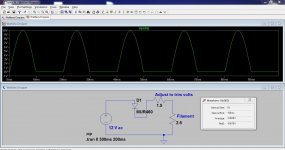
If you really want to run from a 12V secondary, then I would try a diode plus resistor. The half-wave unsmoothed rectification turns the 5V 1.9A heater into a 7.07V 2.7A heater (but for only half the time) so the resistor only has to drop 5V instead of 7V so less power is wasted and less heat generated. The transformer should be OK, as the primary current will balance the secondary current. You will be drawing a little DC from your mains supply, but people do that anyway.
This form of diode dropper was used for the heater chain in some transformerless AC radio/TV sets, although then only for a 300mA chain.
So correct me if I am wrong with the V=IR. I want to take 12vac to 5vac. that is a 7 volt drop. When the heater to the rectifier draws 1.9 Amps in the circuit, that 7volts divided by 1.9Amps, I would get a Resistor value of 3.7ohms.
So power dissipated? 7 Volts x 1.9Amps = 13.3 Watts. Not the worst right? I can source some sturdy power resistors with a 20+ watt rating. I would call this a medium-hot worst case scenario.
Could some sort of X rated capacitor help this scenario out? Or is the amp rating the capacitor killer. Any way to bias more load onto the resistor than the feeble capacitor?
A 3R9 20W Power Resistor would do the job. I think they are actually 25W but it would have to be mounted to the chassis in order to dissipate that amount of heat.
http://www.ebay.co.uk/itm/Resistor-...251?pt=LH_DefaultDomain_3&hash=item5ae9692ee3
http://www.ebay.co.uk/itm/Resistor-...251?pt=LH_DefaultDomain_3&hash=item5ae9692ee3
Last edited:
Also yes! what about the fact that the heater is connected to the cathode? That means the heater floats on top of the 300B+ voltage? or is it below. Does this mean that if one were to use capacitors, would it include the attached B+?
Also along this note… its ok to use DC in the heater circuit with this attached cathode layout?
Also along this note… its ok to use DC in the heater circuit with this attached cathode layout?
So correct me if I am wrong with the V=IR. I want to take 12vac to 5vac. that is a 7 volt drop. When the heater to the rectifier draws 1.9 Amps in the circuit, that 7volts divided by 1.9Amps, I would get a Resistor value of 3.7ohms.
So power dissipated? 7 Volts x 1.9Amps = 13.3 Watts. Not the worst right? I can source some sturdy power resistors with a 20+ watt rating. I would call this a medium-hot worst case scenario.
Could some sort of X rated capacitor help this scenario out? Or is the amp rating the capacitor killer. Any way to bias more load onto the resistor than the feeble capacitor?
The calculations are fine but 13.3 watts is a lot to lose.
The Class X (and Y) capacitor is a totally different thing and used in totally different applications, normally such as across live and neutral and..... this explains it quicker than I can type it
They are small value only.Line-Filter
If the heater floats or is tied to some given voltage then the cap assumes that voltage too but it changes nothing in the way it all works. It just means the cap has (say) 300 or whatever volts DC on both sides of it.
Mooly, I think you would struggle to get 2A out of a reactive PSU.
You mean a simple capacitor, using its reactance ?
I've done it this morning with a 30 Vac tranny, a 270uf/400vdc cap (a small type used as a reservoir cap in a TV/VCR SMPS) and feeding a 5 ohm. That gave 10 volts RMS across the resistor. The cap ran cool.
The winding won't have the same insulation as the leadout wires. However, if the transformer was intended for valve use then it is possible that low-voltage secondaries have sufficient insulation for elevated heater use. A dedicated 5v 2A secondary would be a better guarantee, as transformer winders know that this will be used with an octal rectifier.
That is a complete impossibility: no DC can go through a transformer.The transformer should be OK, as the primary current will balance the secondary current. You will be drawing a little DC from your mains supply, but people do that anyway.
The primary current waveform will be distorted, but will not have any DC component.
Anyway, drawing such a high imbalanced current from a transformer, even a big one, is certainly not a good idea (remember: that is more than 6.5A peak, not negligible at all).
Phase control would be less nasty: at least, the current is balanced.
Instead of speculating contact Brian over at Edcor about the insulation rating of the 12V winding, it may even be included in the specs. Not a hard question to ask.
The dropping resistor is the simplest, safest, and long term most reliable solution you are going to find other than a separate transformer, and a 25W 3.6 ohm power resistor will be fine. Use a sand cast wirewound in free air and there would be no concern about its insulation to chassis.
The dropping resistor is the simplest, safest, and long term most reliable solution you are going to find other than a separate transformer, and a 25W 3.6 ohm power resistor will be fine. Use a sand cast wirewound in free air and there would be no concern about its insulation to chassis.
- Status
- This old topic is closed. If you want to reopen this topic, contact a moderator using the "Report Post" button.
- Home
- Amplifiers
- Power Supplies
- 12 to 5 AC Rectification