A little help about what relay should I chose. I found this and i think that it is elektor circuit, in article it is specified 12V with coil resistance of 1200 ohm, but I have problem to find it, can I put 12V and coil resistance 400 ohm?
or should I change something to use 12/24V with different coil resistance?
thanks
or should I change something to use 12/24V with different coil resistance?
thanks
Attachments
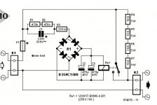
You may reduce the 220R resistance.
But theese mains-coupled devices is DANGEROUS to fiddle too much with.
BNy the way: OMRON G2R-relays is about 1200Ohms for the 12V types.
Tried one of those?
Anyway, before this thread is closed:
I strongly recommend ALL of You guys attempting to make a Softstart cirquit, to build theese with an EXCTRA transformer so You can make the MOST of the softstart on a safe voltage. The resistors and relaycontacts must ofcourse end up in the mains side of it all, but with this extra small transformer giving supply to the to the timing cirquits, most possible of Your build would be within limits and safe.
NOW this thread may be closed.
Last edited:
You may reduce the 220R resistance.
But theese mains-coupled devices is DANGEROUS to fiddle too much with.
BNy the way: OMRON G2R-relays is about 1200Ohms for the 12V types.
Tried one of those?
Actually not but I read the datasheet and they are also in range belove 400ohma
only 24V is near by 1200 ohm
Fear not, the example comes from above:Anyway, before this thread is closed:
I strongly recommend ALL of You guys attempting to make a Softstart cirquit, to build theese with an EXCTRA transformer so You can make the MOST of the softstart on a safe voltage. The resistors and relaycontacts must ofcourse end up in the mains side of it all, but with this extra small transformer giving supply to the to the timing cirquits, most possible of Your build would be within limits and safe.
NOW this thread may be closed.
http://www.diyaudio.com/forums/solid-state/224957-simple-universal-speaker-delay-using-triac.html
or just accept that connecting two transformers within the same enclosure entitles it own safety issues regarding wiring , insulation , creepage distance etc. Using above circuit with an adequate PCB (refer to original article in ELEKTOR from this is ripped off) should be the safest solution , when populated with the right components.
edit:
This was in Elektor 7-8/97 (UK edition).
edit:
This was in Elektor 7-8/97 (UK edition).
Last edited:
In reverse order...
Its being watched and has been from the start")
You can't understand how a circuit such as this operates to ask questions like this. This is why we have such safety concerns with this type of thread.
The capacitor C1 is used as a "wattless dropper" where the reactance of the cap is exploited to limit current. Because the current and voltage are 90 degrees out of phase there is essentially no "real" power dissipated in the cap. It runs cold. So the value of this cap determines the voltage that appears across the relay (look up capacitive reactance). The 220 ohm is a current limiter to keep transient surges within acceptable limits for the bridge rectifier. Depending at what in the mains cycle the circuit is powered up at determines whether this transient is near zero or large.
The quality and type of cap used is crucial for safety and should be a Class X type
The 470K resistors should be specified for the high voltages they could see. The power rating is not enough in itself. Resistors also have max voltage ratings.
Can you see the safety issue if the relay coil went open circuit ?
Probably a good time
.....Anyway, before this thread is closed:
Its being watched and has been from the start
A little help about what relay should I chose. I found this and i think that it is elektor circuit, in article it is specified 12V with coil resistance of 1200 ohm, but I have problem to find it, can I put 12V and coil resistance 400 ohm?
or should I change something to use 12/24V with different coil resistance?
thanks
You can't understand how a circuit such as this operates to ask questions like this. This is why we have such safety concerns with this type of thread.
The capacitor C1 is used as a "wattless dropper" where the reactance of the cap is exploited to limit current. Because the current and voltage are 90 degrees out of phase there is essentially no "real" power dissipated in the cap. It runs cold. So the value of this cap determines the voltage that appears across the relay (look up capacitive reactance). The 220 ohm is a current limiter to keep transient surges within acceptable limits for the bridge rectifier. Depending at what in the mains cycle the circuit is powered up at determines whether this transient is near zero or large.
The quality and type of cap used is crucial for safety and should be a Class X type
The 470K resistors should be specified for the high voltages they could see. The power rating is not enough in itself. Resistors also have max voltage ratings.
Can you see the safety issue if the relay coil went open circuit ?
NOW this thread may be closed.
Probably a good time
- Status
- Not open for further replies.