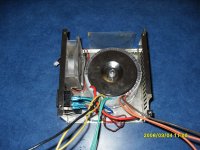
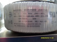
Hi, I have a toroidal transformer that has three output voltages. One set is listed as 15.9V-0-15.9V, the second set is 7.5v, the third is 12.0V-0-12.0V.
My question is, can I use the 15.9V and the 12V outputs together to get 27.9 volts? If so, how. I have tried a few different things , but nothing gives me what I need. Am I chasing my tail here?
Thanks in advance
My question is, can I use the 15.9V and the 12V outputs together to get 27.9 volts? If so, how. I have tried a few different things , but nothing gives me what I need. Am I chasing my tail here?
Thanks in advance
Last edited:
Are the output voltages truely center tapped windings, or can they be separated into 0-15.9, 0-15.9 ? (ie. Does the center tap have 2 wires) Most toroidals I have seen have separated secondary windings.
And your current limit will be as the lowest of the two windings.
The 15.9v set has orange-brown-orange wires, and the 12v set has yellow-black-yellow wires, so I am assuming that since the two CT leads are different colors, that they are separated. I have measured voltage from each CT lead to all of the others and they all produce voltage:
black to yellow gives me 13.25v on both yellow,
brown to orange gives me17.4v on both orange,
brown to yellow gives 9.1v on one and 16.51 on the other,
black to orange gives me 20.73v on one and 13.06v on the other.
Orange to orange is 34.77v,
yellow to yellow is 26.7v
orange 1 to yellow 1 is 33.44v,
o1 to y2 is 7.8v,
o2 to y2 is 26.07v,
black to brown is 3.6v.
Then there are 2 green ones that measure 8.3v between them. I won't go into all of those measurements unless someone asks or thinks it's needed.
Here is a few pics of what I'm working with.
Attachments
That does not make much sense. The label implies separate centre-tapped secondaries, but your measurements seem to show they are connected - unless you are measuring capacitive pickup, which is always possible with a high impedance DMM.orange 1 to yellow 1 is 33.44v,
o1 to y2 is 7.8v,
o2 to y2 is 26.07v,
black to brown is 3.6v.
Could you repeat the orange-yellow and black-brown measurements with a resistor connecting your DMM probes? Anything in the range 10K to 100K will do. The idea is to present a lower impedance than the bare meter, so stray capacitance will have much less effect. I would expect you to see near zero results this time.
That does not make much sense. The label implies separate centre-tapped secondaries, but your measurements seem to show they are connected - unless you are measuring capacitive pickup, which is always possible with a high impedance DMM.
Could you repeat the orange-yellow and black-brown measurements with a resistor connecting your DMM probes? Anything in the range 10K to 100K will do. The idea is to present a lower impedance than the bare meter, so stray capacitance will have much less effect. I would expect you to see near zero results this time.
If they are centre-tapped windings then the answer is no. If they are separate secondaries wired to provide a CT then yes, you can rewire them to get what you want.
Okay, with a 22k resistor I got .044v across the black to brown
orange 1 to yellow 1 is .558v
o2 to y2 is .429v
o2 to y1 is .401v
o1 to y2 is .132v
You were right. That makes a lot more sense. At least for the way it is marked. So I guess the answer is no, all I can get is what's marked on the label.
to be able to stack (add) the voltages you will need to get inside, as Gmp described
Use the 15.9+15.9 as one winding. = >32Vac when open circuit.
Use the 12+12+7as the other winding. =>32Vac when open circuit.
But your output current is limited to 750mAac by the 7Vac winding rating.
A third alternative is to add a 2A rated winding of ~7Vac to make a 31.8Vac + 31.8Vac @ 2A output. That is a total VA of 63.
A lot of work for 63VA !
There is an alternative.If u can get to one of the centre tap and open it to make two separate windings of at least one, u can do
Use the 15.9+15.9 as one winding. = >32Vac when open circuit.
Use the 12+12+7as the other winding. =>32Vac when open circuit.
But your output current is limited to 750mAac by the 7Vac winding rating.
A third alternative is to add a 2A rated winding of ~7Vac to make a 31.8Vac + 31.8Vac @ 2A output. That is a total VA of 63.
A lot of work for 63VA !
Last edited:
to be able to stack (add) the voltages you will need to get inside, as Gmp described
There is an alternative.
Use the 15.9+15.9 as one winding. = >32Vac when open circuit.
Use the 12+12+7as the other winding. =>32Vac when open circuit.
But your output current is limited to 750mAac by the 7Vac winding rating.
A third alternative is to add a 2A rated winding of ~7Vac to make a 31.8Vac + 31.8Vac @ 2A output. That is a total VA of 63.
A lot of work for 63VA !
In addition, the lack of accurate resistance/voltage balance will generate significant amounts of 50/60Hz ripple
to be able to stack (add) the voltages you will need to get inside, as Gmp described
There is an alternative.
Use the 15.9+15.9 as one winding. = >32Vac when open circuit.
Use the 12+12+7as the other winding. =>32Vac when open circuit.
But your output current is limited to 750mAac by the 7Vac winding rating.
A third alternative is to add a 2A rated winding of ~7Vac to make a 31.8Vac + 31.8Vac @ 2A output. That is a total VA of 63.
A lot of work for 63VA !
I was trying to recycle this transformer for use in a LM4780 amplifier. It's my first build and I'm on a limited budget. I guess this is not gonna work for me. I'll need a higher VA than this will provide. From what I've read they like to see about 300, right
 ?
?I have suggested many times my preference for a minimum of 160VA for a power amplifier transformer.
The general guidance spread around this Forum and elsewhere is to use a VA rating between one times and two times the total maximum power of the amplifier/s.
eg.
2 channels of 50W amplifier is 50+50 = 100W of total maximum output power.
Use a transformer with a rating from 100VA to 200VA.
There is a third recommendation to buy and fit the biggest that you can afford.
Rather than start a new thread about this transformer, I'll update this one.
I finally got a transformer for my project that fits my specs.
http://www.antekinc.com/details.php?p=80
This transformer has dual 32v secondaries
http://www.antekinc.com/pdf/AN-4232.pdf
The PCB that I used for my amp has only 3 connection points for the inputs to the rectifiers

I have measured the voltage across the blue and green wires and found that either blue to either green gives me around 32V. Should I cap one of the green wires and use the 2 blue and the remaining green for this connection, or should the 2 green be used together? Or probably there's a better way that I haven't thought of. I plan on using the connections on ESP for wiring the mains(120) minus his bridge rectifier and caps of course.
Power Supply Wiring Guidelines
Here is the schematic for the board

Thanks for your help.
I finally got a transformer for my project that fits my specs.
http://www.antekinc.com/details.php?p=80
This transformer has dual 32v secondaries
http://www.antekinc.com/pdf/AN-4232.pdf
The PCB that I used for my amp has only 3 connection points for the inputs to the rectifiers
I have measured the voltage across the blue and green wires and found that either blue to either green gives me around 32V. Should I cap one of the green wires and use the 2 blue and the remaining green for this connection, or should the 2 green be used together? Or probably there's a better way that I haven't thought of. I plan on using the connections on ESP for wiring the mains(120) minus his bridge rectifier and caps of course.
Power Supply Wiring Guidelines
Here is the schematic for the board
Thanks for your help.
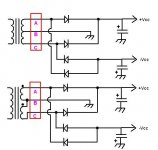
With dual secondaries you should hook them up as in the bottom of the jpg.
The red box shows where the three connections are on the pcb.
The two windings should be connected to give twice each winding when measured.
Example:
A-B 32VAC
B-C 32VAC
A-C 64VAC
Something I noticed:
Looking at the data sheet for the LM4780 suggests a maximum operating supply of 84V or +/- 42V.
A 2 x 32VAC used in this configuration will provide more than 88V or +/- 44V.
( the 94V or +/- 47V maximum rating is for no signal conditions)
None of the graphs in the data sheet go above +/- 40V
(The circuit board is labeled for 28VAC)
Perhaps someone more experienced with these Overture series amps can tell you if this is OK to do.
Hope that helps.
Attachments
Last edited:
The Circuit board is marked 28V, but that should read 28Vdc.None of the graphs in the data sheet go above +/- 40V
(The circuit board is labeled for 28VAC)
IT IS NOT for 28Vac.
Check the traces and determine which is -28Vdc and which is +28Vdc.
The capacitors have the -ve marked with the white bar.
Last edited:
The Circuit board is marked 28V, but that should read 28Vdc.
IT IS NOT for 28Vac.
Check the traces and determine which is -28Vdc and which is +28Vdc.
The capacitors have the -ve marked with the white bar.
You are correct, my error.
It is marked 28V.
But it could be 28VAC and still operate within spec limits.
It does have a bridge rectifier on board.
If you applied +/- 28VDC it would not matter which of the (non-ground) terminals the + and - were connected to...the diodes would direct the supplies to the required polarity.
I just think 32VAC is a bit too much.
Or is that just me?
Can I use this transformer if I run it through 2 FWB rectifiers and voltage regulators? Maybe something similar to this?
LD1585CV - STMICROELECTRONICS - IC, REG LDO, 1.25 TO 28V, 5A, | Farnell United Kingdom
I originally thought that since there were diodes and filter caps on the board that this was the rectifier portion of the circuit. Is that not the case?
Thanks again
LD1585CV - STMICROELECTRONICS - IC, REG LDO, 1.25 TO 28V, 5A, | Farnell United Kingdom
I originally thought that since there were diodes and filter caps on the board that this was the rectifier portion of the circuit. Is that not the case?
Thanks again
Can I use this transformer if I run it through 2 FWB rectifiers and voltage regulators? Maybe something similar to this?
LD1585CV - STMICROELECTRONICS - IC, REG LDO, 1.25 TO 28V, 5A, | Farnell United Kingdom
I originally thought that since there were diodes and filter caps on the board that this was the rectifier portion of the circuit. Is that not the case?
Thanks again
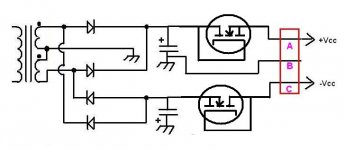
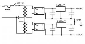
The rectifiers and filter caps are on the board in post #14.
You could build two separate (isolated) regulated supplies as in the jpg.
(don't use LM78xx regulators as the current rating is not high enough.)
I would recommend at least a 10A cct
or
You could rectify and filter before the board and drop the voltage with a couple of power MOSFET's...That way you could still use the transformer you have.
Select high current N-ch with standard gate threshold.
Or wind some extra turns on the transformer and reduce the secondary voltage.
This was covered in another thread.
Or use another transformer.
Attachments
So, I could run the transformer through a couple of rectifier/filters and regulators, and still run it through the rectifier/filter set that is already on the board? Isn't that kind of redundant? I mean, I haven't done this before, so I don't know. Would I lose anything running the rails through 2 rectifiers?
My board is completely assembled already, I just used that pic for reference since it was easier to see everything.
I had actually toyed with the idea of just using external rectifiers/regulators and connecting to the points that the filter caps connect to.
As I say you guys know way more than I.
Thanks for keeping in touch.
- Status
- This old topic is closed. If you want to reopen this topic, contact a moderator using the "Report Post" button.
- Home
- Amplifiers
- Power Supplies
- Using multiple voltage transformer to get higher voltage