Thread closed due to this being an example of an unisolated power supply that is permanently "live" and consequently potentially lethal. Such topics are against the rules for your safety,
http://www.diyaudio.com/forums/site-announcements/167561-diyaudio-rules.html
hi,
i am building a Hbridge SMPS with SG3525 and IR2110, the MOSFETS are IRFP460 i need to know what will be the sufficient deadtime for 50khz frequency???
Because MOSFETs are exploding with 880ns deadtime, is deadtime the problem because it works fine with 60Vdc as input but when i apply 310Vdc booooom
Last edited by a moderator:
What kind of monster are u building?
Drain voltage squared is a factor in switching losses, so u dont need to increase the voltage before it goes too far. You need to increase the voltage slower and observe when the devices temp gets critical.
Can you place current transformers in series with drai and gate to check currents? You'd be able to tweak DT that way. Assuming you have a good o-scope.
IRFP460 are quite sturdy MOSfet's but they have a rather large Ciss witch if not charged fast enough it causes slow turn on and so the power dissipated on the mosfets increases with increasing voltage and they cand be destroyed by this, so you need to be sure you have enough gate current for them. Anyway a schematic is the only way for us to determin what is your problem, so do show us what it is.
Or:
Is your flux walking? How did you prevent that in your circuit?
Is your flux walking? How did you prevent that in your circuit?
A schematic would be useful?
IRFP460 are quite sturdy MOSfet's but they have a rather large Ciss witch if not charged fast enough it causes slow turn on and so the power dissipated on the mosfets increases with increasing voltage and they cand be destroyed by this, so you need to be sure you have enough gate current for them. Anyway a schematic is the only way for us to determin what is your problem, so do show us what it is.
yep. perhaps the duty cycle is becoming too short as the voltage is increased, so short it is not turning the FET on properly....?
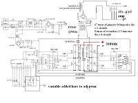
That is a full bridge config, and as i see in the title of the topik you stated that there is a half bridge one, if that is the correct schematic than you maybe have miss stated the config.
In full bridge config the power switches have to cope with all the mains rectified mains voltage, that is 310Vcc in this case, that cannot be a problem for IRFP460 cus they have a 500 voltage rating, but the Ciss i think is the reason for theyr failing, IRFP460 has a Ciss of 4,2n, IR2110 has an output current of maximum 2A, now when charging a cap it first acts like a small shortcircuit so the 10 Ohm resistor limmits that current at something like 1,2A fir 12V Vin for the driver, that could be the reason for theyr failing.
What i think you could do is set the max duty cicle and with a osc visualise the gates of the fets first at that lower voltage and make sure turn on is fast and the wave looks ok than go at the higher voltage to see if things change.
mur1560 are working fine....i have blown (12) IRFP460 and (4) IRFPG50 uptil now
 Which is probably as good a time as any to close the thread.
Non isolated supplies are potentially lethal and are against the forum rules (read notes, section 2)
http://www.diyaudio.com/forums/site-announcements/167561-diyaudio-rules.html
Although the control electronics are fed via a transformer the FET's are not and so there is a direct path back to the unisolated mains. All the primary side is "live".
- Status
- Not open for further replies.
- Home
- Amplifiers
- Power Supplies
- What should be the deadtime for Hbridge circuit???