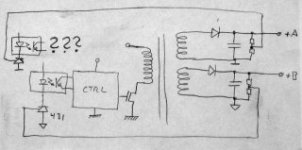
I have a flyback with two separate secondaries which need to be completely isolated from each other.
So far I assume that I also need separate 431 and O.C. because there is no common ground.
correct ?
But how do I mix the signals from both couplers into the controller feedback ?
parallel, series, or any other network ?
So far I assume that I also need separate 431 and O.C. because there is no common ground.
correct ?
But how do I mix the signals from both couplers into the controller feedback ?
parallel, series, or any other network ?
Attachments
Generally you regulate to the highest voltage output, as the fly-back voltage level will change greater there than for any lower voltage winding . The problem with this is that you will experience more voltage drop in the high current low voltage rails as their voltage will change more due to resistive losses in their windings. It's a balance between how you design a transformer and how much regulation that you need.
Or you could just regulate to the most critical rail.
Or you could just regulate to the most critical rail.
Last edited:
Pick one.
OR
Decide that the important part is to limit the maximum output of either supply or the minimum output of either supply.
So, which one is which ?
The 2 output will tend to track, but only one can be regulated. Overcurrent protection should be implemented by sensing the source current of the MOSFET.
No worries, it's a current mode controller, so the source sensing is there.
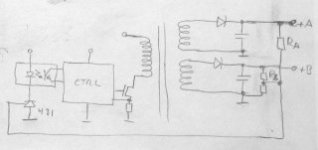
I know how to regulate both - its a compromise but it always worked well for me.
That is its not a problem when both secondaries are referenced to the same ground as in picture #1.
But my problem is how to implement this when the two secondaries are referenced to different grounds as in picture #2.
Attachments

Last edited:
You can always add a tertiary winding and regulate off that. That way, you don't have to show favoritism, instead, both windings get regulated equally poorly. 
If you want to mix optos so they are jointly regulated, you need ratio matched optos. These don't exist, so you're SOL. You can make a far-too-elaborate circuit with some means of signal isolation (i.e., a circuit which copies the error voltage over the isolated boundary, like an ISO122, but without the dollars), and do the ratio mixing from there, but you'll only do as well as the tertiary winding.
Tim
You can always add a tertiary winding and regulate off that. That way, you don't have to show favoritism, instead, both windings get regulated equally poorly.
If you want to mix optos so they are jointly regulated, you need ratio matched optos. These don't exist, so you're SOL. You can make a far-too-elaborate circuit with some means of signal isolation (i.e., a circuit which copies the error voltage over the isolated boundary, like an ISO122, but without the dollars), and do the ratio mixing from there, but you'll only do as well as the tertiary winding.
Tim
The tertiary could be the auxiliary used to supply the controller, no opto needed at all I guess ...
Lets assume I had matched optos ... how would I connect them ? in series or parallel ?
Certainly not in series. If one is 'off' it will block the other.
I don't think you'll get two of these to regulate one switcher, maybe you will, but my bet is they'll fight each other.
Does it matter if the grounds are all separate? The aux windings produce what they do not b/c they have a common secondary ground, but b/c of what current goes thru the windings. Post regulate the secondary not used for sensing.
If you had matched optos, you could use only a resistor on the LED side (no TL431), parallel the photo{transistor|diode} side, and run it normally, using the controller's error amplifier. By varying the load resistor below (or above, as the case may be) the photo{transistor|diode}, you can control output voltage.
But matched optos don't exist. There are fixed-ratio photodiode types, where one LED shines on two photodiodes, one local and one isolated. The gain and ratio must be calibrated once, but the long-term stability and linearity are within a few percent. These are used for analog coupling applications, where you use an error amplifier to set the LED current, using the same-side photodiode for feedback. The isolated-side photodiode carries a proportional current. There is no precision guarantee of the gain or ratio between photodiodes on chip, nor between chips, so each coupler must be calibrated.
A standard LED-phototransistor device has an initial gain variation of about 4:1 or so, with nonlinearity of 2:1 or 3:1 over the full range of currents (~uA to 20mA), and an overall guaranteed range of about 20:1 over temperature, manufacture and aging. Obviously this is no good for trying to match a ratio of voltage outputs, or coupling any kind of signal beyond gross on-off (digital) signals, or coupling a signal within an overall feedback loop (such as TL431 on a single output).
Tim
- Status
- This old topic is closed. If you want to reopen this topic, contact a moderator using the "Report Post" button.
- Home
- Amplifiers
- Power Supplies
- Regulating flyback w/ separate secondaries