Hi peeps,
So I built a nice little headphone amp using a 12au7 and I have been running it off of my DC power supply for a bit when I decided I'd like to make this for my father-in-law but he would need it to be ac capable.
So I decide I am going to make these a two box setup mounted to one small board. A box for the PSU/fuse/switch and a box for the tube amp/ inputs/ volume.I put together a nice enclosure with my transformer and rectifier I test it and everything looks fine.
But after I connect a load to it. In this case I did the amp first with a horrible sound, then I tried a large wirewound resistor. This is what I get
I'm hoping someone here can help me sort this out as it has turned into a bit of a head scratcher for me.
So I built a nice little headphone amp using a 12au7 and I have been running it off of my DC power supply for a bit when I decided I'd like to make this for my father-in-law but he would need it to be ac capable.
So I decide I am going to make these a two box setup mounted to one small board. A box for the PSU/fuse/switch and a box for the tube amp/ inputs/ volume.I put together a nice enclosure with my transformer and rectifier I test it and everything looks fine.
An externally hosted image should be here but it was not working when we last tested it.
But after I connect a load to it. In this case I did the amp first with a horrible sound, then I tried a large wirewound resistor. This is what I get
An externally hosted image should be here but it was not working when we last tested it.
I'm hoping someone here can help me sort this out as it has turned into a bit of a head scratcher for me.
supply
It looks like if you have a bad rectifier it is difficult to judge as it is not clear what the oscilloscope are. From what I can see is that the rectifier is either shorted or built incorrectlyHi peeps,
So I built a nice little headphone amp using a 12au7 and I have been running it off of my DC power supply for a bit when I decided I'd like to make this for my father-in-law but he would need it to be ac capable.
So I decide I am going to make these a two box setup mounted to one small board. A box for the PSU/fuse/switch and a box for the tube amp/ inputs/ volume.I put together a nice enclosure with my transformer and rectifier I test it and everything looks fine.
An externally hosted image should be here but it was not working when we last tested it.
But after I connect a load to it. In this case I did the amp first with a horrible sound, then I tried a large wirewound resistor. This is what I get
An externally hosted image should be here but it was not working when we last tested it.
I'm hoping someone here can help me sort this out as it has turned into a bit of a head scratcher for me.
PSU
Robert if I read the 'scope readings correctly, it is a sine wave, a reservoir cap too small will a give pulsating D.C. even a full wave will be pulsationd at double your supply frequency.
More load needs bigger caps.
If you split the filament current from the rest you can use smaller caps on the low current part.
Robert if I read the 'scope readings correctly, it is a sine wave, a reservoir cap too small will a give pulsating D.C. even a full wave will be pulsationd at double your supply frequency.
The size of cap required to smooth "pulsating DC" is proportional to the current you are smoothing, ie proportional to load. A low value resistor in your tests should make more ripple than a high one given the same caps.Robert if I read the 'scope readings correctly, it is a sine wave, a reservoir cap too small will a give pulsating D.C. even a full wave will be pulsationd at double your supply frequency.
The largest current drawn by a 12au7 headphone amp will probably be going to the filament. The filament is much more tolerant of ripple (some people think AC sounds better than DC here), so you won't need big caps here.
So you can concentrate on properly smoothing the rest of the current, which will be smaller, and so require smaller caps to get the same level of ripple as if you smoothed all the supply in one go.
Last edited:
The size of cap required to smooth "pulsating DC" is proportional to the current you are smoothing.
The largest current drawn by a 12au7 headphone amp will probably be going to the filament. The filament is much more tolerant of ripple (some people think AC sounds better than DC here).
So you only have to smooth the rest of the current, which will be smaller, and so require smaller caps to get the same level of ripple as if you smoothed all the supply.
AGREED
OK everyone.
Thanks for the information.
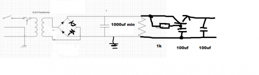
Here is the current psu schematic.
and the schematic for the 12au7 headphone amp I pulled from this very site. I believe the credit goes to Roger gomez.
I'm not sure that the Tube amp is the problem though as any load on the PSU introduces that ripple effect.
From what I'm gathering I probably need to have a more detailed smoothing section after the rectifier.
Does this seem a correct assessment?
Thanks for the information.
Here is the current psu schematic.
An externally hosted image should be here but it was not working when we last tested it.
and the schematic for the 12au7 headphone amp I pulled from this very site. I believe the credit goes to Roger gomez.
An externally hosted image should be here but it was not working when we last tested it.
I'm not sure that the Tube amp is the problem though as any load on the PSU introduces that ripple effect.
From what I'm gathering I probably need to have a more detailed smoothing section after the rectifier.
Does this seem a correct assessment?
Your bridge rectifier is wired incorrectly... maybe just a typo ") The two right hand diodes both need to be the other way round.
The two right hand diodes both need to be the other way round.
More smoothing yes The 47uf cap could usefully be a little bigger. Try at least 1000uf.
The centre tap from the tranny can be left floating. As it is you must ensure that it does not connect to the negative rail of the amp as if it does it will short out one winding of the tranny via the bridge rectifier.
The two right hand diodes both need to be the other way round.More smoothing yes
The 47uf cap could usefully be a little bigger. Try at least 1000uf.The centre tap from the tranny can be left floating. As it is you must ensure that it does not connect to the negative rail of the amp as if it does it will short out one winding of the tranny via the bridge rectifier.
Your bridge rectifier is wired incorrectly... maybe just a typo
More smoothing yes
The centre tap from the tranny can be left floating. As it is you must ensure that it does not connect to the negative rail of the amp as if it does it will short out one winding of the tranny via the bridge rectifier.
Thanks. The rectifier was a stock image in visio. I am actually using a full wave bridge rectifier so I know it's wired correctly. I'll try a larger cap. Thanks!
I've just seen in the small print your note about the diodes
Anyhow you want the transformer wired like this with the ground connection to be the from the zero volt point.
Whether you add any power supply regulators depends on the voltage the amp needs to work and the voltage you actually measure across the reservoir cap in the PSU. A 7812 type needs around 2.5 volts or more differential so you would need 14.5 volts minimum across the cap to use one. If you have less than that then a good option is an active ripple filter using a transistor a resistor and cap. These are just guestimate values. The transistor would be a medium power high gain device (preferably) like a TIP41C
Attachments
I've just seen in the small print your note about the diodes
Anyhow you want the transformer wired like this with the ground connection to be the from the zero volt point.
Whether you add any power supply regulators depends on the voltage the amp needs to work and the voltage you actually measure across the reservoir cap in the PSU. A 7812 type needs around 2.5 volts or more differential so you would need 14.5 volts minimum across the cap to use one. If you have less than that then a good option is an active ripple filter using a transistor a resistor and cap. These are just guestimate values. The transistor would be a medium power high gain device (preferably) like a TIP41C
Mooly,
Thank you for your help.
Perhaps you can help my understanding with regulators. I have read that it is not always wise to use a regulator in front of an audio circuit because the demands from the music require more or less passages depending on the transients and dynamics of the music.
Do you believe this to be true?
well, you're going to have to get another regulator for the filaments.Yup, just checked again. 18.5 volts. No load attached. Yes the primary is matched to my mains.
Mooly,
Thank you for your help.
Perhaps you can help my understanding with regulators. I have read that it is not always wise to use a regulator in front of an audio circuit because the demands from the music require more or less passages depending on the transients and dynamics of the music.
Do you believe this to be true?
That's more applicable to larger power amplifiers where an unregulated supply can deliver more "power" on transients. Imagine your 18 volts or so powering an amp driving speakers. Short term 18 volts is available supplied via the reservoir caps (although this voltage will quickly fall under sustained load). So lets say 18 volts peak to peak (thats 9 volts peak or around 6 volts RMS). For an 8 ohm speaker that equates to 4.5 watts RMS (for a brief moment on a transient until the supply collapses). If the amp were on a regulated supply of 12 volts then the power under all conditions, transient and continuos would be only 2 watts RMS. Both amps would have the same "continuous" RMS power rating because the 18 volt rail collapse down to 12 volts in a few 10's of milliseconds under load. The unregulated one would have "better" transient ability.
For your headphone amp the most important thing is to ensure the filament volts is correct. Is it 12 ? or 12.6 ? Also the power involved driving headphones is of the order of a few milliwatts so transient ability doesn't even figure into it. The regulator already used in your amp is nothing to do with the power supply but is used as a constant current load for the FET output.
What you really need to confirm before all this though is what the voltage is under load i.e. running the amp properly (with a 1000uf or more reservoir cap) because that voltage determines what kind of regulation or filter can be used. If the voltage falls under load to around 14 or so then a normal 7812 type regulator isn't suitable because there isn't enough "extra" voltage to work with.
With 18 volts available you should use a proper regulator such as a 7812.
http://www.datasheetcatalog.org/datasheets/150/44435_DS.pdf
Three pins, in, out and ground. All you need add is two caps of around 10uf close to the regulator pins to decouple input to ground and output to ground. The regulator would need a small heatsink.
Lets see what we are working with first
- Status
- This old topic is closed. If you want to reopen this topic, contact a moderator using the "Report Post" button.
- Home
- Amplifiers
- Power Supplies
- Help with PS under load.