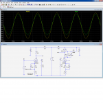
I made this flyback for tube preamp.
Problem is I have low voltage.
What I did:
- Input 16V
Primar:
- 8 turns of 3x1mm diameter wire
Secundar:
- 13 turns, should give 20V, it gives 11V, with 10k pot at max
- 110 turns, should give 200V, it gives 130V, with 10k pot at max
I did try other orientation of diode, it gave much less voltage. PCB wiring and mass is made properly for high frequency.
I can add more turns, but it doesn't make sense bearing in mind many calculations I saw in books and schematics.
What is going on?
An externally hosted image should be here but it was not working when we last tested it.
Problem is I have low voltage.
What I did:
- Input 16V
Primar:
- 8 turns of 3x1mm diameter wire
Secundar:
- 13 turns, should give 20V, it gives 11V, with 10k pot at max
- 110 turns, should give 200V, it gives 130V, with 10k pot at max
I did try other orientation of diode, it gave much less voltage. PCB wiring and mass is made properly for high frequency.
I can add more turns, but it doesn't make sense bearing in mind many calculations I saw in books and schematics.
What is going on?
Last edited:
Are the windings closely interleaved?
Yes.
Is IRF510 big enough for the amount of power you intend to draw, and is the 0.22 ohm shunt resistor small enough as well?
IRF510 is cold totaly.
There should be a resistor in series with the 0.01 capacitor between COMP and FB, try 10k.
100k is there, I put it.
You could increase the value of 470k to compensate ?
What to put? 1M?
However you need to gap the core.
At least a 1mm gap is required to stop the transformer saturating.
Also if the transformer gets hot the gap will again help stop saturation.
Core is cold.
There is no gap. Should I make it on all 3 pillars of 'E'? To put 1mm paper between?
Let us suppose the flyback operates just in critical mode, this means the On time will be 7µs, the peak current will reach 4.8A, requiring a primary inductance of 17µH.Its EI-33 core form 350W ATX.
If the material is typical of its application, the core will have a Al of ~=4000.
With 8t, this results in an inductance of 256µH. Way too much.
For 4.8A^ and 0.35T^, the minimum number of turns required is ~=2.5, so you are OK with your 8t, but you have to insert a total airgap of 0.666mm.
If the core is totally ungapped and you create it with a spacer, the spacer needs to be 0.33mm.
The IRF510 will work, but it is rather light for such an application, and this will lead to severe conduction losses when the circuit operates normally
You guys rock. I gaped it, and changed 470k with 1M, and now I have 2-3 x higher voltage.
Elvee, can you point me to some tutorial on web where I can read about smps transformer calculus? What you just wrote.
What I noted UC3843 is not suitable to give much power on low voltage, because of its I-sense pin 3, I've put there 0.1R, and it can't give more than 30W on 16V.
Only problem I have now is that circuit wont operate below 14V, which is strange, UC3843 should work above 7V. I don't know what is the cause?
There are many sources, this for example:Elvee, can you point me to some tutorial on web where I can read about smps transformer calculus? What you just wrote.
2001 Magnetics Design Handbook - MAG100A
Designing high-current chokes is easy | EDN
You lose ~1V in your FR102, plus an unknown amount due to ohmic losses in the 100µH, and the combined drop plus the ripple could be sufficient to trigger the UVLO at 8.2VOnly problem I have now is that circuit wont operate below 14V, which is strange, UC3843 should work above 7V. I don't know what is the cause?
Thanks for links.
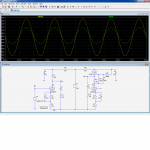
I tried supply with this PCL82 SE amp, and it works perfect. There is absolutely no noise.
I use it with guitar on input and 32R headphones or 8R speaker. I'd like some more volume on headphones, but I insist that triode is first to pick up signal, and pentode on output, so some mini FX loop seems to be logical solution. I'd like to add BJT or FET between triode and pentode, on 180V, with current mirror perhaps. Do you have some circuit for suggestion?
I tried supply with this PCL82 SE amp, and it works perfect. There is absolutely no noise.
An externally hosted image should be here but it was not working when we last tested it.
I use it with guitar on input and 32R headphones or 8R speaker. I'd like some more volume on headphones, but I insist that triode is first to pick up signal, and pentode on output, so some mini FX loop seems to be logical solution. I'd like to add BJT or FET between triode and pentode, on 180V, with current mirror perhaps. Do you have some circuit for suggestion?
For what purpose? Additional voltage gain?I'd like to add BJT or FET between triode and pentode, on 180V, with current mirror perhaps. Do you have some circuit for suggestion?
I don't think it is reasonable: the first stage already has quite a high gain, near that of a µ-amplifier, and anyway the whole amplifier is closed-loop: just increasing the loop gain will lead you into troubles, since there is a transformer in the loop.
Also, the external gain will remain almost unchanged anyway.
Moreover, inserting a semiconductor gain stage would alter the tube character of the amplifier. If you go that way, it is simpler to simply get rid of the glass completely.....
Your best bet is to alter the feedback ratio, by reducing the 100ohm cathode resistor for example.
If you are concerned by the loading from the pentode, Miller effect, etc, you can add an active anode load acting simultaneously as a µ-amplifier and as SRPP impedance adapter.
You will get a marginally higher gain, a lower output impedance, and a minimally intrusive addition from a tube perspective.
Anyway, I am not a tube guy, and you should ask a moderator to move this part of the discussion to the tube section, people there will be in a better position to advise you.
Here is the comparison between the original and the actively loaded version, with and without load.
The MOS is a small, low capacitance one, it could also be a high voltage jFET with adapted resistors values.
Attachments
What to put? 1M?
Core is cold.
There is no gap. Should I make it on all 3 pillars of 'E'? To put 1mm paper between?
Yes that's what I did, I used some cardboard on all 3 legs with a SMPS and it was ok.
...I gaped it, and changed 470k with 1M, and now I have 2-3 x higher voltage...
Flyback PSU always needs air gap, there are many info sources, you just need pacience to go trugh them.
On the other hand, UC3843 has the noninverting imput of it's error amp connected to an internal voltage of 2,5V, so that is the voltage level needed at feedback pin witch is the inverting imput of the error amp, so let say the 200V output with the lower side of the divider a 10K pot plus a 10K resistor, that makes 20k, now 2,5v divided by 20k Ohms equals 125 micro amps that is the current of the divider, now for 200V on the output the upper resistor must be like this: 200V-2,5V=197,5, that is from the output 200 needed we substract the 2,5V needed for the error amp, and we got 197,5V left, now we divide that to the current of the divider and we get 197,5/125u=1,5M Ohms, so that is how the divider should look for the 200V needed, any other voltage levels can be easy calculated this way, you just need to know the voltage level at the EA imputs and establish a divider current witch is also the EA imput current and from that you can choose a the wright resistors, i would take out the 10k resistor between the Fb pin and the divider, it only makes the upper resistor needed that much higher.
")
- Status
- This old topic is closed. If you want to reopen this topic, contact a moderator using the "Report Post" button.
- Home
- Amplifiers
- Power Supplies
- SMPS number of turns