Not on my account, please. I was rather hoping you'd try including flux density.
No, not solely on your account. It seems that I tried to make things much easier than they actually are, so without a more realistic model I'm not producing any meaningful results. And as I said before, knowing every single parameter of a given transformer and include it in the simulation is way too much for my taste. That's why I see no point in doing simulations any further but rather pick a commodity tranny with suitable VA rating and that's it. Didn't mean to offend you, though
 .
.Simulating transformers is quite intriguing nonetheless, I've already learned some more about transformers and spice
.It would be daft to value what you have by what you haven't.
... sorry, didn't get that
When I use music in my spice, I get noise and distortion from a straight piece of wire
Do you mean wave input or even a simple sinusoidal voltage source? Don't know how good your German is, but you may have a look at my homepage: Klirrfaktor simulieren mit LTspice preamp.org. You can find all the relevant data in the pictures.
Absolutely the way to go if you can do it and have the time. Most of my experience is with valves, for which it's normal to use transformers made with audio in mind, and plenty are available. For low-voltage audio, choice and availability seems more limited, perhaps because commodity-grade items are so common and cheap. Since I have only just stumbled into the 1980s, perhaps I haven't found the good stuff yet.
This wasn't the best place to raise my gripe, perhaps. It appears common in low-voltage DIY audio to use bigger transformers than necessary. Presumably this is in an effort to reduce sag during loud bits. Although this may be true, if it is done just by over-specifying a commodity-grade transformer, the chances are it will be noisy exactly when it needs to be quietest...during the quiet bits.
Perhaps everyone uses shunt regulation?
i do wind my own traffos even for solidstate amps using the same consideration as with tube amps.....
transformers that are noisy can be quieted down, just take a few steps which the average diyer can do on his own i think....
perhaps you in the sates or any other place using 120 volt mains can try using this traffos with dual 110 volt primaries and hooking them up in series and then connecting them to the mains, of course the secondaries will be halved so get one with twice your requirement or get two of them and wire teir secondaries in series as well....you will be rewarded with a cool running traffo and a quiet one to boot......
Made a more comprehensive simulation. This time I used the complete P3A circuit with a 2 Ohm resistive load and an actual wave file as input source. The power supply consists of a single rectifier bridge for both rails, 10.000uf of capacitance for each rail, and two modeled transformers.
Simulation time was almost four hours versus a quarter; the generated raw files grew to a full 36GB and 1GB, respectively.
#1: Elaborate Model, 5 seconds of music into 2 Ohms, positive voltage rail shown
#2: Simple Model, 5 seconds of music into 2 Ohms, positive voltage rail shown
#3: Elaborate Model, section of 0.5 seconds for better resolution
#4: Simple Model, section of 0.5 seconds for better resolution
#5: Overlay of both models for direct comparison, Simple one shown in red
#6: amplifier output voltage
Can you try the sim again with 80,000 uf instead of 10k......
i do wind my own traffos even for solidstate amps using the same consideration as with tube amps.....
transformers that are noisy can be quieted down, just take a few steps which the average diyer can do on his own i think....
perhaps you in the sates or any other place using 120 volt mains can try using this traffos with dual 110 volt primaries and hooking them up in series and then connecting them to the mains, of course the secondaries will be halved so get one with twice your requirement or get two of them and wire teir secondaries in series as well....you will be rewarded with a cool running traffo and a quiet one to boot......
Tony did you ever finish that low z amp you were designing ...?
Ok , its the one in your sig .....
it is a work in progress also, kids in my side of the ocean have this obsession with power, the first thing they ask when they see a project posted is how to increase the rails for more power...i merely gave them an alternate view on things.....i hope to finish that amp in the future, thanks for asking.....
Can you try the sim again with 80,000 uf instead of 10k......
Yes. It's running now, hopefully I find the time to post the results this evening.
Here you are. 
Attachments
I recently developed an Excel spreadsheet to model this kind of power supply, connected to a class-AB amplifier that is driving a resistive load. Here is a link to the spreadsheet:
http://audio.claub.net/software/PS_dimensioning/Power_Supply_capability_calculations_VER2.2.xls
There are similarities with your results, but I did not include ESR of the caps.
-Charlie
Charlie, I appreciate this very, very much. It helped me get my head around how transformers and power supply caps affect system performance. I've needed this visual badly - thank you!!!
John
Here are the comparison charts. I used the simulation model from Tom Gootee with the measured data of my trafo.
The first chart shows both models with a simple resistive load on the ac, where the blue line resembles Tom's model and the red line my simple approach.
On the other charts the models were loaded with a full bridge rectifier, 4700uF (ESR=63m) and the stepped resistor. Same colour coding here.
Unfortunately I don't have a transformer with lower VA and equal voltage rating at hand. This would have made the comparison much more descriptive.
Please note that these comparison charts took more than half an hour to simulate, while the simple model is only a matter of seconds
Preamp,
I don't know if this is too late for your purposes or not. (Sorry. I didn't see this thread until now.) But the transformer model that I used (from measurements) has been "per-unitized" so that it is scalable.
That means that you can change the VA rating, the output voltage rating, the mains frequency, and/or the input voltage, and new spice model parameters will be automatically generated.
Recently, I also included the auto-scaling transformer model in a spreadsheet that simulates a transformer-rectifier-capacitor power supply with a constant-current load, by using a numerical solution of the differential equations for the circuit. It is downloadable at:
http://www.diyaudio.com/forums/power-supplies/216409-power-supply-resevoir-size-166.html#post3282260
This should point to a screen image of the main user interface:
http://www.diyaudio.com/forums/atta...er-supply-resevoir-size-v0.99scrn_prezoom.jpg
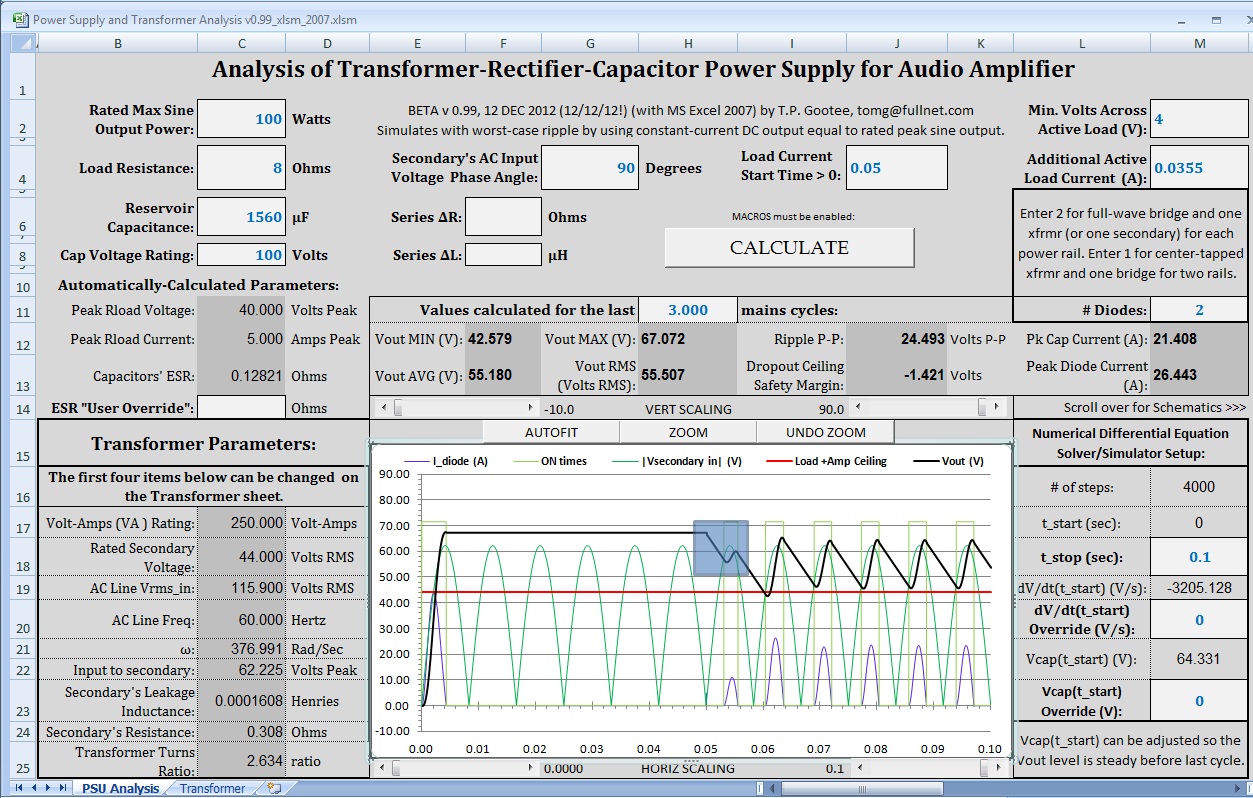
(Ignore the small blue rectangle on the plot. I was just showing how the Zoom feature worked.)
If you want the latest version of my LT-Spice PSU simulation files that use the scalable transformer model, let me know. The latest version lets you set the transformer model's scalable parameters in the main circuit's .asc file. So you can easily step-sweep them, for example.
P.S. This is a newer transformer model, from a more-recently measured transformer. The first one was not a great transformer. I'm not sure which one you have been using but if it's the earlier one, I recommend switching to the newer one.
Cheers,
Tom
Last edited:
- Status
- This old topic is closed. If you want to reopen this topic, contact a moderator using the "Report Post" button.
- Home
- Amplifiers
- Power Supplies
- Transformer voltage droop