hi all.
I'm quite new around here, and I finally decided to go for a diy amp. I chosen the P3A amp from "Elliott Sound Products", which seems both to sound pretty good and to be quite easy to build (this is my first amp, I just built a preamp till now).
Now to my questions:
I'm making the shopping list, and I'm in the PSU fase (300VA, 2x25V).
So I need a bridge rectifier + caps and I'm looking for suggestions. I intend to more or less follow the suggestions you find here: 60-80W Power Amplifier, but maybe with some more capacitance and some snubbering (or not?)
For caps, I really have no clue. On mouser.com you can find anything from 2 to 20 euros.. Can somebody suggest me a name? I'm more the "El-cheapo" kind of guy rather that the "Louis Vuitton - or nothing", but I'd like to build something "serious" and I really have no clue how much price/brand matters.
For the bridge rectifier, I think I'd go for a all-in-one solution rather than soldering 4 separate diodes together, but again: can somebody give me a name for a >=35A rectifier?
Thanks all in advance
AC
-For the bridge rectifier there are 2 things to take care of: 1-The voltage rating, it has to have a reverse voltage breakdown higher than the maximum anticipated rectified voltage, so in your case a PSU of +/-35Vcc needs a bridge rectifier with the voltage rating higher than 70V, actually there are many bridge rectifiers that have a voltage rating of 200+ so they are easy to choose from; 2-The current rating, the bridge rectifier has to have a current rating higher than the maximum anticipated load current, so if the load needs for example a maximum of 5A you need a bridge rectifier of minimum that, at least double is recommended. There is no need to worry about things like forward voltage drop, turn off time, and other stuff like that in rectifying voltage at 50/60Hz ( linear PSU's ).
-In choosing the filter caps for linear PSU there are also 2 main things to worry about: 1-The voltage rating, the cap needs a voltage rating greater than the maximum anticipated filtered voltage ( Vpp ), one easy and safe way i choose them is Vcap=Vpp*1,3, so in your case 35V*1,3=45V, evidently you will choose the 50V available one; 2-The othe main thing to take care of is it's cappacity in uF, there are rather complicated formulae to calculate the exact needed cappacity but they are not always needed, just use as high a cappacitor as possible cus the higher the cappacity the lower the mains hum, a good amplifier has a good PSRR so there is no need to get huge cappacity, as i sayd about 10, or maybe max 20mF would be more than enough. There are other things that makes a cappacitor different from another, souch as current ripple rating, temperature rating, and things like that but linear PSU are not that sensitive so you do not need to worry about that many things. One thing you could do is use 2 or more smaller caps in parallel, there are some benefits with this way.
-In choosing the filter caps for linear PSU there are also 2 main things to worry about: 1-The voltage rating, the cap needs a voltage rating greater than the maximum anticipated filtered voltage ( Vpp ), one easy and safe way i choose them is Vcap=Vpp*1,3, so in your case 35V*1,3=45V, evidently you will choose the 50V available one; 2-The othe main thing to take care of is it's cappacity in uF, there are rather complicated formulae to calculate the exact needed cappacity but they are not always needed, just use as high a cappacitor as possible cus the higher the cappacity the lower the mains hum, a good amplifier has a good PSRR so there is no need to get huge cappacity, as i sayd about 10, or maybe max 20mF would be more than enough. There are other things that makes a cappacitor different from another, souch as current ripple rating, temperature rating, and things like that but linear PSU are not that sensitive so you do not need to worry about that many things. One thing you could do is use 2 or more smaller caps in parallel, there are some benefits with this way.
the bridge rectifier is cheap. No special specs required. For capacitors there are many choices, For a 50Hz application, ripple current rating and lifetime would be the main things to look for. 5A ripple should be OK you can use the generally cheaper RB or snap in devices if the look or mounting is not a problem Can and screw terminal electrolytics get a bit expensive but they often have long lifetimes and look nice. There is nothing wrong with using say four 2700uF capacitors to get 10000uF, I had to do that recently just to meet an ESR spec Forget anything with the word audio in the name, SMPS duty is much more demanding and the capacitors tailored for that duty are reasonably priced. Hope that helps, there is really too much choice and this is not a demanding application.
Use an R+C snubber across each diode to help avoid ringing, if any, in the rectifier/transformer circuit.
A Capacitor alone is very unlikely to attenuate the ringing and in some cases can make the ringing worse.
But, if there is no ringing on the supply line then don't bother adding the snubber.
A Capacitor alone is very unlikely to attenuate the ringing and in some cases can make the ringing worse.
But, if there is no ringing on the supply line then don't bother adding the snubber.
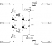
If performance is seeked then maybe something more complicated but with way better results can be used, D1 and D2 are zenner diodes with voltage ratings of Vout needed plus about 1,4V that drops on the tranzistors, for best performance and max transistor current the Vin-Vout difference should be between 5 and 10V, that guarantees at least 5A from TIP35/36C, and you get the advantage of stabilised PSU for the amplifier ( if more current is needed then 2 or more pairs of transistors can be used with emitter resistors for better current sharring ), the other advantage of the circuit is that R1+C1/R4+C4 form a low pass filter that pushes any noise signall on the supply line below the audio spectrum ( about 1,3Hz ), and further more it is also a capacitance multiplier, C2 and C3 are multiplied by Hfe times, they see a load of Iout/Hfe, so smaller caps just after the bridge rectifier can be used without any problem. All of this comes at a price, the power transformer need more voltage at it's outputs ( about 5-6V ) and there will be some important power dissipated by the transistors so a heatsink is needed, but for amplifiers souch as this P3A that are used for house hold ussage good quality sound is verry important so i think it is worth it.
Attachments
Last edited:
- Status
- This old topic is closed. If you want to reopen this topic, contact a moderator using the "Report Post" button.
- Home
- Amplifiers
- Power Supplies
- 2 capacitors and a rectifier