This sketch is from reverse engineering of a 100W Flyback SMPS.
Date code on components suggests it may be 2003 vintage.
I want to understand how the PFC works.
The controller is good old 3842 current mode and there is only one power MOSFET.
In textbook PFC there should be two, one in the boost and one in the flyback.
So it might be a single stage PFC.
1) Is this PFC at all ?
2) Active or passive ?
3) Is this a viable and known topology ?
4) If so - how does it work ?
5) Efficient ? Low part count at least ...
Attachments
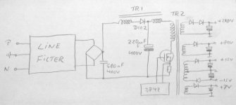
It is an ordinary flyback supply. I'm pretty sure you have made an error in your reverse engineering. The TR1 winding between the 220 uF cap and TR2 certainly doesn't look right.
nope - no error !
TR1 is a separate transformer core similar but smaller than TR2 which is the flyback trafo.
And quite different from the common mode line filters which are in front of the bridge.
The two windings before and after D102 are on that additional core and thus inductively coupled.
And then there is that diode in between ...
Now that I discovered and added another diode D107 to the diagram (which I overlooked and therefore omitted in the OP) it looks quite similar to Fig.8a and Fig.10 in this document: http://www.freepatentsonline.com/5734562.pd
So it is text-book single-stage PFC after all... though somewhat out-of-date maybe.
Now the question remains, what exactly is the 2nd winding on TR1 doing, coupled to the 1st winding which corresponds to L1 in the literature.
Sensing the current in the primary of the flyback TR2 and feedback to the boost stage ... ?
Attachments
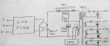
yes it is PFC - its a combined boost/flyback converter
assuming its drawn correctly, it looks like the RHS TR1 winding is pulling some energy from the DC bus cap into the flyback transformer while D107 & LHS TR1 are doing the boost bit. without analysing it in detail, it looks like the result will be to draw current with a sinusoidal envelope (if the LHS TR1 winding subtracts from the DC bus voltage) but thats more guess than analysis
assuming its drawn correctly, it looks like the RHS TR1 winding is pulling some energy from the DC bus cap into the flyback transformer while D107 & LHS TR1 are doing the boost bit. without analysing it in detail, it looks like the result will be to draw current with a sinusoidal envelope (if the LHS TR1 winding subtracts from the DC bus voltage) but thats more guess than analysis
- Status
- This old topic is closed. If you want to reopen this topic, contact a moderator using the "Report Post" button.
- Home
- Amplifiers
- Power Supplies
- Is this PFC or not ?