Hello,
I have a little DIY project for a class-A amplifier, 4-channels @ ~10W each. It consists in a simple common-emitter gain stage followed by an emitter-follower output, biased with a CCS.
I use a large Hammond transformer, 36VAC with center tap (unused-floating) for 0V-46VDC supply rails, rated 432VA. Rectification is via a large bridge that mounts on the heatsink. This is followed by 8x10000µF Panasonic caps, 63V/105°C.
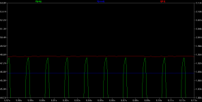
Each channel draws ~1.91A at idle, so total current is 7.64A. The formula I/(2*F*C) gives me ~800mV of ripple. I measure ~600mV.
The problem is that I hear this ripple as a hum in the output, as it modulates the signal. I guess I'm just stuck with this ripple figure, as the math predicts it. Increasing capacitance would quickly become ridiculous IMO and not get me to un-noticable levels. Is there anything that can be done outside of adding regulation?
I don't think it's a grounding problem either. I have the AC mains ground connected to the all-metal chassis. DC and signal ground is separate from chassis and uses short runs of thick gauge wire. Any resistance there will be under 10mili-ohm and never cause such a voltage (600mV) to develop at the worst-case 1.91A current.
Thanks,
IG
I have a little DIY project for a class-A amplifier, 4-channels @ ~10W each. It consists in a simple common-emitter gain stage followed by an emitter-follower output, biased with a CCS.
I use a large Hammond transformer, 36VAC with center tap (unused-floating) for 0V-46VDC supply rails, rated 432VA. Rectification is via a large bridge that mounts on the heatsink. This is followed by 8x10000µF Panasonic caps, 63V/105°C.
Each channel draws ~1.91A at idle, so total current is 7.64A. The formula I/(2*F*C) gives me ~800mV of ripple. I measure ~600mV.
The problem is that I hear this ripple as a hum in the output, as it modulates the signal. I guess I'm just stuck with this ripple figure, as the math predicts it. Increasing capacitance would quickly become ridiculous IMO and not get me to un-noticable levels. Is there anything that can be done outside of adding regulation?
I don't think it's a grounding problem either. I have the AC mains ground connected to the all-metal chassis. DC and signal ground is separate from chassis and uses short runs of thick gauge wire. Any resistance there will be under 10mili-ohm and never cause such a voltage (600mV) to develop at the worst-case 1.91A current.
Thanks,
IG
A single-ended amplifier (0-46Vdc vs. dual-ended +/-23Vdc) will have very little power supply rejection. It will be more sensitive to ripple on the supply.
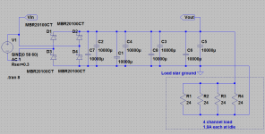
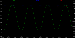
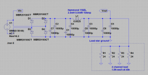
If you can sacrirfice 2-3 volts of supply voltage, try adding some 0.1R resistors between the caps to form a CRCRCRC filter. 20W rating on the resistor between the leftmost two caps, 10W on the other two. Put the load ground where shown at the rightmost cap, below, to keep the filter loop currents before the load. Star ground your load(s), but don't star ground the filter sections. Wire the CRC filter sections as a ladder as shown to keep the filter ripple currents within each loop. The leftmost 2 caps that are fed from the bridge need to have a minimum ripple current rating of around 8A each or so, 2A minimum each for the middle 2 caps and 0.5A for the rightmost 2. So if your 8 10MF caps have a ripple current rating of at least 8A or so they are fine to use in all 8 cap positions.
If you can sacrirfice 2-3 volts of supply voltage, try adding some 0.1R resistors between the caps to form a CRCRCRC filter. 20W rating on the resistor between the leftmost two caps, 10W on the other two. Put the load ground where shown at the rightmost cap, below, to keep the filter loop currents before the load. Star ground your load(s), but don't star ground the filter sections. Wire the CRC filter sections as a ladder as shown to keep the filter ripple currents within each loop. The leftmost 2 caps that are fed from the bridge need to have a minimum ripple current rating of around 8A each or so, 2A minimum each for the middle 2 caps and 0.5A for the rightmost 2. So if your 8 10MF caps have a ripple current rating of at least 8A or so they are fine to use in all 8 cap positions.
Attachments
Last edited:
A capacitance multiplier is what I had come down to after doing a bit more research. This project had been shelved for a couple of years and I actually intended to use one back then, but just forgot since. It won't hurt that I might have to reduce my bias levels also, the heatsinks get hotter than I'm comfortable with.
IG
IG
my guess is, with the mentioned audible hum, that the problem lies mostly with the biasing of the transistors. make sure you use capacitors for bypassing the resistive biasing to the bases even if it means splitting a single resistor into two (usually unequal parts) to insert a capacitor for hum filtering.
A single-ended amplifier (0-46Vdc vs. dual-ended +/-23Vdc) will have very little power supply rejection. It will be more sensitive to ripple on the supply.
If you can sacrirfice 2-3 volts of supply voltage, try adding some 0.1R resistors between the caps to form a CRCRCRC filter. 20W rating on the resistor between the leftmost two caps, 10W on the other two. Put the load ground where shown at the rightmost cap, below, to keep the filter loop currents before the load. Star ground your load(s), but don't star ground the filter sections. Wire the CRC filter sections as a ladder as shown to keep the filter ripple currents within each loop. The leftmost 2 caps that are fed from the bridge need to have a minimum ripple current rating of around 8A each or so, 2A minimum each for the middle 2 caps and 0.5A for the rightmost 2. So if your 8 10MF caps have a ripple current rating of at least 8A or so they are fine to use in all 8 cap positions.
I could sacrifice a few volts. Thanks for doing the sim. I'll input that into AIMspice to see what it gives me.
my guess is, with the mentioned audible hum, that the problem lies mostly with the biasing of the transistors. make sure you use capacitors for bypassing the resistive biasing to the bases even if it means splitting a single resistor into two (usually unequal parts) to insert a capacitor for hum filtering.
You mean bypassing the ground to base resistors? I'm not certain I follow, or at least can't see how this'd be done without affecting the signal.
IG
Seems like the simplest thing to do at this point in my build might be to split my 8x10000µF capacitor bank into 2x40000µF and insert a choke in-between. Common-mode ferrite-donuts are pretty cheap and 4x7.3mH would reduce the ripple to a simulated 12mV, low enough IMO. It would also reduce buzz by smoothing-out the sawtooth ripple into a quasi-sinusoidal waveform.
IG
IG
That should work, but I'm not seeing any place the ripple would appear as common mode. Those CM chokes are most useful for conducted EMI. May need to be a standard choke like a Hammond 159ZL:
159ZL - HAMMOND - CHOKE | Newark
http://www.hammondmfg.com/153.htm
159ZL - HAMMOND - CHOKE | Newark
http://www.hammondmfg.com/153.htm
Attachments
Last edited:
I think the ferrite core on those will go into saturation if used in differential mode. Here is some info, 5th paragraph down:
Application Notes: How To Select And Use Ferrite/Nanocrystalline Common Mode Chokes : CWS Coil Winding Specialist, manufacturer of transformers, inductors, coils and chokes
But those CM chokes are cheap enough you could give it a try! Whatever impedance they wind up producing may be enough to do the job.
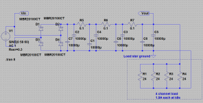
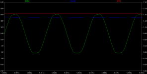
Another thought is just one 0.25 ohm 20W resistor between the two 40mF cap banks, rather than the 3 0.1Rs. The results are nearly as good.
Application Notes: How To Select And Use Ferrite/Nanocrystalline Common Mode Chokes : CWS Coil Winding Specialist, manufacturer of transformers, inductors, coils and chokes
But those CM chokes are cheap enough you could give it a try! Whatever impedance they wind up producing may be enough to do the job.
Another thought is just one 0.25 ohm 20W resistor between the two 40mF cap banks, rather than the 3 0.1Rs. The results are nearly as good.
Last edited:
I'll be trying some of these common-mode chokes, a couple of these are already on they way to me. They're pretty cheap in any case. ") I'll see if they work, but I get it now that the core might indeed saturate in differential mode.
I'll see if they work, but I get it now that the core might indeed saturate in differential mode.
They Hammond chokes have too much DCR for my application, I would have to had planned for them from the start or to lower my power output as it stands.
If the CM chokes don't do it, I wonder if the primary or secondary winding of a small transformer might do?
IG
I'll see if they work, but I get it now that the core might indeed saturate in differential mode.They Hammond chokes have too much DCR for my application, I would have to had planned for them from the start or to lower my power output as it stands.
If the CM chokes don't do it, I wonder if the primary or secondary winding of a small transformer might do?
IG
The common-mode donut chokes do seem to be saturating. They have some effect, but no where near what simulation predicts. Tiny power resistors do help out, but not enough on their own. It's kind of hard finding something that'll happily pass the 8 amperes required. The secondary winding of a small Hammond 166L24 transformer I have has under 1ohm DCR and I measured its inductance at ~43mH. This one worked really well and took down ripple to ~20mV. It was unfortunately on the fast track to heath-death and would not have lasted more than a few minutes IMO.
IG
IG
try using a transformer out of a dead microwave oven.
Use the existing coils. take off the existing I of the EI and re-attach using paper as a gap filler in the EI.
You now have a gapped EI choke. and it cost you nothing.
Vary the gap to see what effect it has on inductance and saturation, if any.
Use the existing coils. take off the existing I of the EI and re-attach using paper as a gap filler in the EI.
You now have a gapped EI choke. and it cost you nothing.
Vary the gap to see what effect it has on inductance and saturation, if any.
try using a transformer out of a dead microwave oven.
Use the existing coils. take off the existing I of the EI and re-attach using paper as a gap filler in the EI.
You now have a gapped EI choke. and it cost you nothing.
Vary the gap to see what effect it has on inductance and saturation, if any.
That's where my thinking was leading me, large salvage transformers, microwave sounds good for this. I might have a couple of regular cheap power transfos to try first though.
~30mH and up might be good and DCR should stay below ~1.5 ohm.
IG
post 7 .......demeterart
+1
I might consider this down the road, but killing the hum at the source seems like a worthy first step IMO.
IG
CRC or CLC instead of C alone.
I always use the analogy of rCRC rather than omitting the leading r.
When you use C alone that missing r when replaced gives rC. You are using a filter with very little filtering effect due to the small r.
When you put in a real and useful R, the filter attenuates the hum much more.
I always use the analogy of rCRC rather than omitting the leading r.
When you use C alone that missing r when replaced gives rC. You are using a filter with very little filtering effect due to the small r.
When you put in a real and useful R, the filter attenuates the hum much more.
CRC or CLC instead of C alone.
I always use the analogy of rCRC rather than omitting the leading r.
When you use C alone that missing r when replaced gives rC. You are using a filter with very little filtering effect due to the small r.
When you put in a real and useful R, the filter attenuates the hum much more.
I had some mild success with some CRC attempts around 1ohm last night. I also have burn marks on my fingers.
8 amperes is a lot for anything above 0.1ohm.IG
- Status
- This old topic is closed. If you want to reopen this topic, contact a moderator using the "Report Post" button.
- Home
- Amplifiers
- Power Supplies
- Ripple in unregulated supply for class-A amp