we know you "hear" differences - but they may not caused by the circuit's behavior
naive "just listen" is sadly "the mode" on many sites - despite more than overwhelming evidence in perceptual psychology and specifically psychoacoustics that controls with measurements exceeding our casual "by ear" level, frequency response matching is required - to have valid subjective listening results
a blinding protocol is also a requirement
fast switching gives improved reliability/resolution in controlled psychoacoustic listening tests - minutes of time swapping components degrades our ability to discern differences - much less hours or days between major circuit mods, buttoning up the amp, reinstalling it in the system...
.. then listening for changes with full knowledge of what you did to the circuit at each stage
but practically everyone is introduced to audiophiledom through florid magazine reviews, reports by Golden Eared Gurus, reinforced by exchanges with others in the bubble and their own naive subjective experiences listening for sound changes with expectations primed by this social construct
and these naive subjectivists usally take pointers to the science as a personal attack on their honesty, experience - rather than accepting human limits, testing the science themselve by trying the controlled listening
Last edited:
naive "just listen" is sadly "the mode" on many sites - despite more than overwhelming evidence in perceptual psychology and specifically psychoacoustics that controls with measurements exceeding our casual "by ear" level, frequency response matching is required - to have valid subjective listening results
a blinding protocol is also a requirement
fast switching gives improved reliability/resolution in controlled psychoacoustic listening tests - minutes of time swapping components degrades our ability to discern differences - much less hours or days between major circuit mods, buttoning up the amp, reinstalling it in the system...
.. then listening for changes with full knowledge of what you did to the circuit at each stage
but practically everyone is introduced to audiophiledom through florid magazine reviews, reports by Golden Eared Gurus, reinforced by exchanges with others in the bubble and their own naive subjective experiences listening for sound changes with expectations primed by this social construct
and these naive subjectivists usally take pointers to the science as a personal attack on their honesty, experience - rather than accepting human limits, testing the science themselve by trying the controlled listening
hey jcx,
agreed, and what you're saying makes sense. At the end of it all, it has to
be your own ears
 and perception that makes the decision, not someone else's hearing or vested interests.
Thanks again for your help, I'll keep posted on how the CCS's turn out.
Gary
CCS sounds....worse??
Hi,
This is a tale of an amplifier that, according to everything I've read, heard and even simulated about CCS, have yet to materialize.
Since I first posted in this thread, I've learned quite a bit about CCS arrangements, perhaps enough to understand different topologies and the ability to not only simulate them in LTSpice, but to simulate them in an LTSpice model of my amplifier and see what the result is - even though simulation isn't the holy grail, and I understand that.
I have a transformer coupled push-pull parallel amplifier in full Class A mode. Since I've built it, it has used a simple arrangement in the LTP cathodes, a 15K resistor. Has it sounded good? Yeah, it's good. But like any audio nut-case, I'm always looking for ways to improve the sound. I know that the screen and driver regulators fall short; I'm using a "Maida" style regulator for both 350V and 400V tasks. Knowing the improvement the SSHV2 had for my DAC in the tube gain stage and the low voltage supplies, I'm just waiting for a few boards to arrive so I can then replace those linear regulators with the SSHV2.
In the meantime, I wanted to experiment with different CCS arrangements. To this point, I've tried a bipolar cascode using a single LED a bipolar using 2 LED's, a single 10M45, and a cascoded MOSFET pair using a DN2540 and a IXTP01N100D (this one today in fact)
The result...none of them made the sound better, in fact, the amplifier sounds hard and grainy in the midrange. What I am hearing, is totally against what I have seen in simulation. In the case of the single 10M45, with the 6SN7's using 33K plate resistors (I had used a 39K/33K with the cathode resistor) and a nominal 9.5mA cathode current, simulation showed a distortion of 0.18% at 40W output. When I got it in the shop, and "tuned" the CCS with the adjustable trimmer, I was able to get that down even lower, about 0.17%. Yes, I realize a tenth is much to talk about and just not significant; I mention it to show agreement from simulation to test. I'm using an HP8903B audio test set, with 1KHz tone. I couldn't wait to put the amp back together, and have a listen. I was not only dismayed, but at a loss to explain how THD could be half, but with the nasty midrange I was hearing. Although admittedly, there was better resolution and definition, it would not take long to get listening fatigue.
So I went back to LTSPice looking for an answer, and I thought after looking carefully at the FFT of the CCS, I might have found it. It appears that the lower distortion was predominantly 3rd order (which is normal for a push-pull amplifier, correct?) but fairly low, about -59dB (relative). I also understand that 3rd order harmonics sound dissonant and hard. Looking at plots of "nice" single ended amplifiers shows nice decaying spectrum, so I thought that maybe I should have a higher second harmonic to mask the nasty third. By adjusting the plate resistor value on one side of the LTP, I was able bring up the second harmonic to -55dB, while pushing the 3rd down to -59dB. It showed THD at 0.37% for full power, a little higher but not unreasonable for a push-pull tube amp, I think. I thought this was the fix, so I proceeded not only to adjust the one plate resistance, but to install the second CCS using the cascoded FET pair. I shop tested it and again the I tuned the CCS for lowest distortion at various power levels. Again, eager to get it back on the system and give it a try....but...
Once again, surprise. It sounds just marginally better than what I had just tested before the change. Now I have to say, this whole adventure has me totally mystified. With lower distortion, even lower 3rd order than just a cathode resistor, does this sound "not as good"?? Is it my linear regulators that don't want to play nice with the CCS, or something funky going on with a CCS in the LTP coming out in the power stage? The one variable that's fairly constant (don't mind the oxymoron) is that what I see in the shop agrees with what I measure, so the simulation seems to be good...fair. But what I am hearing just doesn't equate.
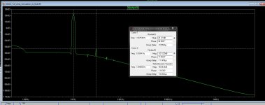
I've attached 3 diagrams from simulation, the first is "Original_Quad_Push-Pull" which shows LTSpice of the FFT using just a cathode resistor.
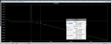
The second is "Quad_Push-Pull_with CCS_1", using a 10M45 CCS with 10mA current and 33K plate resistors on both sides.
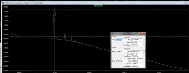
The third is "Quad_Push-Pull_with CCS_2" which has the cascode FET CCS, set to 9.5mA, and the slightly unbalanced plate resistors (one at 33K, the other at 35.2K) to bring up the second harmonic. From this it's pretty clear that the 3rd harmonic remained the same; and the second is dominant by over 5dB. Yet....it still does not sound right.
In searching for an answer to this issue, I found a very interesting thread on a forum about using a CCS in the cathodes:
I would avoid CCS on the cathodes - Lynn Olson - Tube DIY Asylum
I'm not sure if the writer was referring to any cathode based CCS topology, but found this interesting. This problem must be unique to me, because it goes against anything I've understood about the benefits of a CCS.
Any guesses? Is it the regulators...? Poor bandwidth, too high Zo?
Any help....or suggestions would be appreciated.
Gary
Hi,
This is a tale of an amplifier that, according to everything I've read, heard and even simulated about CCS, have yet to materialize.
Since I first posted in this thread, I've learned quite a bit about CCS arrangements, perhaps enough to understand different topologies and the ability to not only simulate them in LTSpice, but to simulate them in an LTSpice model of my amplifier and see what the result is - even though simulation isn't the holy grail, and I understand that.
I have a transformer coupled push-pull parallel amplifier in full Class A mode. Since I've built it, it has used a simple arrangement in the LTP cathodes, a 15K resistor. Has it sounded good? Yeah, it's good. But like any audio nut-case, I'm always looking for ways to improve the sound. I know that the screen and driver regulators fall short; I'm using a "Maida" style regulator for both 350V and 400V tasks. Knowing the improvement the SSHV2 had for my DAC in the tube gain stage and the low voltage supplies, I'm just waiting for a few boards to arrive so I can then replace those linear regulators with the SSHV2.
In the meantime, I wanted to experiment with different CCS arrangements. To this point, I've tried a bipolar cascode using a single LED a bipolar using 2 LED's, a single 10M45, and a cascoded MOSFET pair using a DN2540 and a IXTP01N100D (this one today in fact)
The result...none of them made the sound better, in fact, the amplifier sounds hard and grainy in the midrange. What I am hearing, is totally against what I have seen in simulation. In the case of the single 10M45, with the 6SN7's using 33K plate resistors (I had used a 39K/33K with the cathode resistor) and a nominal 9.5mA cathode current, simulation showed a distortion of 0.18% at 40W output. When I got it in the shop, and "tuned" the CCS with the adjustable trimmer, I was able to get that down even lower, about 0.17%. Yes, I realize a tenth is much to talk about and just not significant; I mention it to show agreement from simulation to test. I'm using an HP8903B audio test set, with 1KHz tone. I couldn't wait to put the amp back together, and have a listen. I was not only dismayed, but at a loss to explain how THD could be half, but with the nasty midrange I was hearing. Although admittedly, there was better resolution and definition, it would not take long to get listening fatigue.
So I went back to LTSPice looking for an answer, and I thought after looking carefully at the FFT of the CCS, I might have found it. It appears that the lower distortion was predominantly 3rd order (which is normal for a push-pull amplifier, correct?) but fairly low, about -59dB (relative). I also understand that 3rd order harmonics sound dissonant and hard. Looking at plots of "nice" single ended amplifiers shows nice decaying spectrum, so I thought that maybe I should have a higher second harmonic to mask the nasty third. By adjusting the plate resistor value on one side of the LTP, I was able bring up the second harmonic to -55dB, while pushing the 3rd down to -59dB. It showed THD at 0.37% for full power, a little higher but not unreasonable for a push-pull tube amp, I think. I thought this was the fix, so I proceeded not only to adjust the one plate resistance, but to install the second CCS using the cascoded FET pair. I shop tested it and again the I tuned the CCS for lowest distortion at various power levels. Again, eager to get it back on the system and give it a try....but...
Once again, surprise. It sounds just marginally better than what I had just tested before the change. Now I have to say, this whole adventure has me totally mystified. With lower distortion, even lower 3rd order than just a cathode resistor, does this sound "not as good"?? Is it my linear regulators that don't want to play nice with the CCS, or something funky going on with a CCS in the LTP coming out in the power stage? The one variable that's fairly constant (don't mind the oxymoron) is that what I see in the shop agrees with what I measure, so the simulation seems to be good...fair. But what I am hearing just doesn't equate.
I've attached 3 diagrams from simulation, the first is "Original_Quad_Push-Pull" which shows LTSpice of the FFT using just a cathode resistor.
The second is "Quad_Push-Pull_with CCS_1", using a 10M45 CCS with 10mA current and 33K plate resistors on both sides.
The third is "Quad_Push-Pull_with CCS_2" which has the cascode FET CCS, set to 9.5mA, and the slightly unbalanced plate resistors (one at 33K, the other at 35.2K) to bring up the second harmonic. From this it's pretty clear that the 3rd harmonic remained the same; and the second is dominant by over 5dB. Yet....it still does not sound right.
In searching for an answer to this issue, I found a very interesting thread on a forum about using a CCS in the cathodes:
I would avoid CCS on the cathodes - Lynn Olson - Tube DIY Asylum
I'm not sure if the writer was referring to any cathode based CCS topology, but found this interesting. This problem must be unique to me, because it goes against anything I've understood about the benefits of a CCS.
Any guesses? Is it the regulators...? Poor bandwidth, too high Zo?
Any help....or suggestions would be appreciated.
Gary
Attachments
I put my 6V6 line preamp on CCS load once testing what I could gain over the resistor load it had before, measured clearly lower THD, but I did not like it at all and reverted back to its resistive load.
Salas, was your CCS in an LTP as mine is?
What did you find about the sound that wasn't good?
Gary
It was on the anode of a trioded single ended 6V6GT line pre. While I got more clarity, it got pinched and mechanical also. Artificial result, like high bit rate MP3 kinda. When I put BJT TO-92 cascode to the cathode of a Schmidt phase splitter in my KT88 push pull trioded power amp it was an improvement though. It fixed the AC balance, while the amp still got 2nd harmonic predominant. I had used 12AT7 to push towards that. Just an AC heated 20W stereo single midi size box amp with non choke filtered B+ and a 250W toroid smack in its belly next to signal cables and input tubes.
Attachments
It was on the anode of a trioded single ended 6V6GT line pre. While I got more clarity, it got pinched and mechanical also. Artificial result, like high bit rate MP3 kinda. When I put BJT TO-92 cascode to the cathode of a Schmidt phase splitter in my KT88 push pull trioded power amp it was an improvement though. It fixed the AC balance, while the amp still got 2nd harmonic predominant. I had used 12AT7 to push towards that. Just an AC heated 20W stereo single midi size box amp with non choke filtered B+ and a 250W toroid smack in its belly next to signal cables and input tubes.
Your description of the sound would almost mirror what I am hearing. If that's your actual FFT plot, very impressive performance. I guess what I really need to understand is, can any CCS improve the sound of just a resistor in the LTP? Perhaps I need to try a different BJT; the FETs don't sound so good.
I've tried a 2-LED reference MJE-340 cascoded to a BC550C, but wasn't much more impressed by that either.
Its the actual FFT plot on ARTA measurement suite. Low level not to burn the sound card, a couple of volts on 8 Ohm resistor load. Check out what was going on inside. Third party service man's dream... But here is the CCS area schema if it gives you any clue. Design and spaghetti execution, yours truly.
Third party service man's dream... But here is the CCS area schema if it gives you any clue. Design and spaghetti execution, yours truly.Attachments
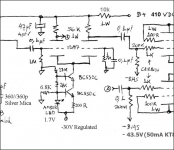
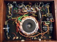
Its the actual FFT plot on ARTA measurement suite. Low level not to burn the sound card, a couple of volts on 8 Ohm resistor load. Check out what was going on inside.
The only impression that really counts is how it sounds, and knowing how fussy you are, I'll bet it's great. Since the 1st to 5th service guys are likely called "Salas", getting it fixed should be a snap!
Thanks for the schematic. Since I'm direct coupled, I have to stick with higher voltage parts on the first device.
One thing I need to consider is that perhaps some of what I'm hearing might be stage overload. My understanding is that a CCS in the cathodes can be easily overdriven and will readily produce 3rd order harmonics when that happens. So I'm going to tweak the first stage driver in spice to see how that plays out.
Between that and the SSHV2 regulators, perhaps that's all it will need. I'll keep posting on results.
Just a quick rule of thumb- the DN2540 cascodes don't really work well until you have 10mA or more of current through them. Bipolar cascodes are much better in this regard. Also, make sure you have sufficient voltage across the CCS so it doesn't run out of compliance on signal swings (most important in plate circuits). That is, you want the voltage to accommodate any expected swing plus leave at least ~20 more volts across the CCS.
Just a quick rule of thumb- the DN2540 cascodes don't really work well until you have 10mA or more of current through them. Bipolar cascodes are much better in this regard. Also, make sure you have sufficient voltage across the CCS so it doesn't run out of compliance on signal swings (most important in plate circuits). That is, you want the voltage to accommodate any expected swing plus leave at least ~20 more volts across the CCS.
Hi SY,
Thank you for taking the time to respond. Since my grids are DC drive from the front end @ 95V, I have sufficient cathode voltage to keep the CCS happy. As for the 10mA, in it's current state, bringing up the current from it's present 9.5mA, or even 10.5mA doesn't seem to displease the 6SN7's, in spite what I've read about optimal current at 8mA.
I'm not stuck on using FETS; having no expereince with CCS to this point they seem to be the favorite. However, I will happily take another run at a bipolar, again using an MJ340 and a BC550C. My first try resulted in less than stellar performance, I'm not sure if it was related to using 2 LED's in the BC550 reference? This time I'll go with a single but higher voltage (as Salas has done) and see how that works out.
Again, I believe that the stage has become more sensitive to drive so this could be part of the problem. I'm getting 2Vp higher than before without touching anything else, so driving the 6L6GC grids harder could result in additional thirds being generated in the push-pull. I'm working on optimizing all front end values to minimize 3rd order distortion in the LTP.
Regards,
Gary
8mA is a minimum for the 6SN7s- they'll work fine at 10mA as long as you watch plate dissipation.
Guys,
Thanks again for your responses, very helpful. I'll make the front end changes tonight on my amplifier and report back on what I hear. I suspect it will make all the difference I am expecting at this point with the present regulators.
Gary
2 SSHV2 regulators have been installed; 1 for the driver supply (375V) which requires about 20mA; current adjusted to 40mA. It''s working fine.
The other is the screen supply (350V) which requires about 60mA at full output; adjusted to 80mA.
Unfortunately, it looks like the SSHV2 doesn't like the load the screens are presenting. Looks like it was oscillating, and caused some issues with the cathode bias, where the cathodes voltages on the tubes went anywhere from 14V up to 25V. (They were all previously adjusted at 19V). Finally, the SSHV2 output dropped to 300V but maintained current. I disconnected it and ran it again just on the load and it seems to be OK. (350V, 80mA incl. 20mA shunt current) I tested screen current draw on my last regulator, it's not constant, requiring a few mA at idle and about 60mA at full load.
Would the SSHV2 have some defining parameter that would make it difficult to drive a finicky load such as screens? I'm using 100 ohm screen resistors right at the pins. The linear regulator I was using before (the Maida) didn't have any of these issues.
Gary
Yes there will be situations that it can be at phase odds. Especially when anode regulation is there too. Do both regulators draw from same voltage source? Can you show the power tube stage circuit detail? Maybe we can work around that by tweaking the screen reg a bit.
Hi Salas,
Find attached the LT Spice model.
Another odd thing; the heat sink I have it attached to is quite big and more than adequate (bigger than the picture I posted before). Input voltage the same. Yet, the temperature of the device is around 70C when running. I'm monitoring current and voltage, both are running at spec. It did not get this warm with just the 5.85K resistive load.
Something odd going on...perhaps oscillations. I'm going to scope it and see what might be there.
Gary
Attachments
Scope could confirm, if the CAT rating of your probe at x10 is safe. But screen is dynamic and spares 60-70mA reg CCS at low swing. So that could explain heat too. Do you have 1uF 400V capacitor to replace the now 0.33uF so we can increase the termination to see what happens?
- Status
- This old topic is closed. If you want to reopen this topic, contact a moderator using the "Report Post" button.
- Home
- Amplifiers
- Power Supplies
- Replacement for 10M45 / CCS