Yes there will be situations that it can be at phase odds. Especially when anode regulation is there too. Do both regulators draw from same voltage source? Can you show the power tube stage circuit detail? Maybe we can work around that by tweaking the screen reg a bit.
I missed your question. The plate supply comes in around 430V and feeds both regulators.
I scoped the screen supply, and nothing odd there; just 10mV of noise. Where the trouble starts is when I apply a signal to the input; the cathode voltages go wild. I already trashed 1 tube so I don't want to apply an input signal until I have this figured out.
*I miss pentode2 symbol to run the .asc but I see the diagram. R28,29 100 Ohm for real, yes?
Salas,
Here's corrected model with the installed screen resistors (100 ohms) Also find the model for the "pentode 2"
Ignore the frequency response; the transformer is modeled without real parasitic values. The model was to verify overall correctness, voltage values and distortion plots.
Attachments
So you scoped the screen pin with the reg on and its DC line when no signal goes to the tube?
Sorry, we're a little out of sync. I just uploaded good files.
Yes, that's right, I scoped with 350V DC at screen resistor, with no signal in and there's no funny stuff.
Now it deploys well but I will have to add models since you got an include text I would naturally miss. So, 4 screens in parallel from a shunt reg that does not do funnies but when signal goes to tubes they go biasing all over the place...Hmm...The change from Maida is now the voltage source to screens has 25 times the closed loop bandwidth and much lower Zsource in high band too. It could have been the reg facing some load with capacitive characteristics that chokes its phase margin but that would have manifested immediately on idle. The tubes don't like the shunt reg's voltage source characteristics I am afraid when they are driven with signal. In your shoes I would up the screen resistors to highest permissible, change the 0.33uF on the reg to 1uF and give it a try with any spare low cost or bit worn out tubes in case some screen goes poof. If it would still don't go well, I would forget the idea of using this shunt reg in that amp for screens, and save the extra SSHV2s for other compatible applications in the future.
Now it deploys well but I will have to add models since you got an include text I would naturally miss. So, 4 screens in parallel from a shunt reg that does not do funnies but when signal goes to tubes they go biasing all over the place...Hmm...The change from Maida is now the voltage source to screens has 25 times the closed loop bandwidth and much lower Zsource in high band too. It could have been the reg facing some load with capacitive characteristics that chokes its phase margin but that would have manifested immediately on idle. The tubes don't like the shunt reg's voltage source characteristics I am afraid when they are driven with signal. In your shoes I would up the screen resistors to highest permissible, change the 0.33uF on the reg to 1uF and give it a try with any spare low cost or bit worn out tubes in case some screen goes poof. If it would still don't go well, I would forget the idea of using this shunt reg in that amp for screens, and save the extra SSHV2s for other compatible applications in the future.
Salas,
Sorry, I missed your post asking about the 1uf/400V capacitor. I do have one.
I have measured the screen before and it "idles" with no signal in around 4 or 5mA. At full voltage in, around 1.8V, I measured 3V across a 50 ohm resistor and it dropped 3V (60mA) This is RMS; the model's predicted value is
about 70mA.
However, I've bottom mounted both power devices so it will take me awhile to take it apart to change it out. While it's apart, I might used a more thermally conductive heat pad on the IRF840 so it's spot temperature doesn't get so high.
Either way...I need to remove the regulator to change the cap or to just go back to the Maida linear regulator. However, what do you think are the chances of success with 470 ohm resistors, and the 1uF capacitor? Changing all the screen resistors will be a pain. I know that they will ultimately affect the sound, so I wouldn't want to go more than 470 ohm.
Attached is the tube model lib from Norman Koren's archive.
Gary
Attachments
Gary, with 470 Ohms there is a chance the screens will get some extra damping enough to make them happy with their new DC voltage source, but its only a hypothesis to test. Just not to retreat on first no go by the tubes. Can't predict. You could just piggyback the cap for testing on the existing 0.33u for 1.33u total. So not to dismantle now. But its your choice testing. Maybe no cigar.
Gary, with 470 Ohms there is a chance the screens will get some extra damping enough to make them happy with their new DC voltage source, but its only a hypothesis to test. Just not to retreat on first no go by the tubes. Can't predict. You could just piggyback the cap for testing on the existing 0.33u for 1.33u total. So not to dismantle now. But its your choice testing. Maybe no cigar.
OK...I realize it's a difficult thing to know, given the nature of the circuit, layout and other variables. However, I'm first going to use the old Maida screen regulator in lieu of the SSHV2 to ensure nothing else is amiss. If that works OK in the circuit alongside the SSHV2 feeding the driver/splitter circuit, I will then change the cap and grid resistors and try again the SSHV2 on the screen supply. One thing I should have mentioned is that when I had the Maida regs installed, I was using a 100uF Jensen cap at the output (linear regs like this anyhow) and I'm sure this capacitance had a lot to do with the stability of the linear regulator. As we know, it doesn't do much for the overall performance though.
I do have one further question. I am using a common point ground post for every single ground connection in this amplifier. That is, every ground goes to this point. I have the FORCE & SENSE 0's of the SSHV2's tied to this point.
I did not tie anything to the input ground of the SSHV2 PCB since it is already common with the FORCE 0 line. Should this cause any problem? I think when using this grounding method it is the correct way to do it, unless there is an issue with the remote sensing. It doesn't appear to affect the operation but maybe there's more to it?
Last edited:
Sense and force look for the nearest return point that the consumption node refers to. If you have a sub star for the 4 cathode resistors, take those lines there, and tie input separately where the PSU that feeds the reg returns.
That's a bit tricky. I designed a "bias PCB" that's on the back of my amplifier. It contains a fixed resistor and a pot in series, both bypassed by a 220uF electrolytic. Each tube has a bias control. The output transformers are from a Sansui AU-111 that used an 8% cathode feedback tap winding. They come out of the transformer as an orange and white lead. One of them ties to ground internally. The transformer also has a separate ground wire. I used the transformer's ground wire to the star ground point, as the original AU-111 did this as well. They must have had good reason to do this (not tying the orange or white lead to GND), so I did not want to change.
In short, the ground post is the closest point for the cathode resistors, via the transformer. Everything, even the power supply ground coming in, is tied to the ground post. My thinking was that if all grounds return to this common point, then everything should be equalized. It must work well because the amplifier has a -89dB SNR which it would not attain with poor grounding. This tested on an HP8903B audio analyzer, in calibration.
I confirmed about an hour ago I may have toasted more than 1 power tube.

This evening I will replace all the power tubes with a used set, and retest using the Maida on screens and the SSHV2 on the driver/splitter. I will then try the 1uF cap on the SSHV2 screen regulator, along with the higher cathode resistors. I'll keep you posted Salas and thanks for the help.
If nothing else, this may be helpful information for someone else trying the SSHV2 in the same application.
It can take a 100uF output cap with 0.2-0.3 Ohm ESR as your before config too. 1.8R position be a short in that case. Limits the reg's bandwidth but keeps the flat extended low Z.
Salas,
I have again discovered a problem where I can only point to me
During the course of installing the new regulators, I updated the pre/driver PCB. There are "unmarked" connection points on the PCB where the coupling caps are connected. During reassembly I inadvertently swapped on one channel those tie points. No wonder the cathodes were going a bit crazy. I had to think about where this exact incident had happened before. I remembered that during my amplifier bench prototyping 3 years ago, I did the same thing. Once I recalled that, I looked for a swapped connection and discovered it. I had a very late night, last night. I should have realized this much sooner...I went as far as re-connecting my old power supply regulator PCB and once seeing the same thing was happening, knew it was something DUMB!!!!

After reconnecting the SSHV2's, I'm happy to say that your SSHV2 is STELLAR driving the screen load! Absolutely no issues, even with 100 ohm screen resistors. The cap is a 0.47uF (did not have a 0.33uF)
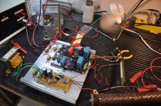
So now the only concern is spot heat on the IRF840. (see attached picture) The other PCB is the DC filament regulator w/cathode reference and fan supply. The chassis has a low volume, super quiet fan to move air through it from the bottom out the right side.
After running it for about 15 minutes with the amplifier playing, the IRF840 is measuring about 65C to 72C, measured directly on the metal tab of the device with an IR tool. I'm thinking this is a bit high, and would like to get it down. I'm presently using a mica insulator with thermal compound, and it's mounted on a flat aluminum surface That heatsink is heavy; the fins underneath extend at least 3cm from the backplate.
I'm thinking of trying a higher thermal conductivity silver bearing paste, but this might not do much as the thermal conductivity of the mica insulator may be the limiting factor. Do you know of a better method to use?
Is 70C a bit high for the IRF840? In your experience, what should the maximum ever be for reliable operation? Going by the data sheet it appears the de-rating is significant past 70C.
Gary
Attachments
Its customary you get a troublesome mishap but all works for you soon. Happy end is what matters.
65-72C with 1C/W RthetaJC device like the 840 is not too taxing if it does not burn more than 10 to 20W on average. It breaks at 125C internally, but less average means more life in all electronics. It should get its max standing temp on idle signal. How high it goes for 840 case temp if you leave it alone without signal? Say for 30 mins. Look for German Keratherm insulators. Red. Watch out for some conductivity with Arctic Silver and the like, this is HV. Some state they are zero conductivity, others state some degree.
65-72C with 1C/W RthetaJC device like the 840 is not too taxing if it does not burn more than 10 to 20W on average. It breaks at 125C internally, but less average means more life in all electronics. It should get its max standing temp on idle signal. How high it goes for 840 case temp if you leave it alone without signal? Say for 30 mins. Look for German Keratherm insulators. Red. Watch out for some conductivity with Arctic Silver and the like, this is HV. Some state they are zero conductivity, others state some degree.
Its customary you get a troublesome mishap but all works for you soon. Happy end is what matters.
65-72C with 1C/W RthetaJC device like the 840 is not too taxing if it does not burn more than 10 to 20W on average. It breaks at 125C internally, but less average means more life in all electronics. It should get its max standing temp on idle signal. How high it goes for 840 case temp if you leave it alone without signal? Say for 30 mins. Look for German Keratherm insulators. Red. Watch out for some conductivity with Arctic Silver and the like, this is HV. Some state they are zero conductivity, others state some degree.
Customary?? I hope it's a custom that ends pretty soon!!
This is the thermal paste I was referring to:
Noctua.at - sound-optimised premium components "Designed in Austria"!
It's NON-electrically conductive (I mentioned silver by mistake) so I'll give that a try. Those thermal pads you mention aren't carried here. The best alternative I could find is this:
http://ca.mouser.com/Search/ProductDetail.aspx?R=4170Gvirtualkey53210000virtualkey532-4170
4170G, made by Aavid. They are aluminum oxide and appear to have a higher thermal conductance than the mica. I'll order them and see how they work out.
I will also try the test you are suggesting; I'll idle the amp with no signal and check the temperature after 30 minutes. I'm probably over-worried, the maximum device temperature (Vishay) is 150C, and I'm not half way there yet. Although your sentiments are exactly mine on the issue of heat: in a case such as this, cooler performance results in better "in-spec" performance and longer life.
The real report I want to post is...the sound. Hopefully I can do that in a day or 2.
Last edited:
- Status
- This old topic is closed. If you want to reopen this topic, contact a moderator using the "Report Post" button.
- Home
- Amplifiers
- Power Supplies
- Replacement for 10M45 / CCS