Thanks once again for checking the mods. I have just finished installing them, and it still works! Amps are warming up as I type.
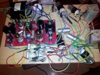
Picture of the bird's nest attached.
I have kept two 100uF caps after the final output from the power supply board - I know you didn't recommend this but have added some additional resistors in series between the caps so hope that is acceptable?
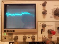
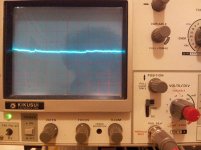
I tried measuring noise/ripple with the scope. There is a significant drop in noise or ripple after the additional caps on the output. I'm not sure I was using the scope correctly, but set it to DC coupled and tried measuring both AC and DC. AC showed more fluctuation. I've attached a couple of photos of the trace. Both are with voltage range set at the maximum resolution of 0.1mV per division. The worst case one is with magnification set to x5 and measured at the final output from the board. The smoother trace is at 0.1mV with no X5 magnification and measured after one of the additional 100uF caps after the output.
I tested before and after the low pass filter mod and think it really did clean up some of the high frequency hash.
I'm not sure if the result would be considered good or not? or if I was measuring correctly. I think there was some residual ripple on the scope as there best results looked similar to when the probes weren't even connected to the power supply - i.e. the scope must be picking up some residual noise. This was particularly apparent when positioned close to the power supply.
Thanks Nigel, the large voltage drop would explain the heat. I have ordered some 12 volt valves (12SN7) like you suggest. I then read that 12SX7s are supposedly better. Guess I can always try some later.
Thanks all for you help with this there does seem to be more texture and authority to the sound now.
Oh, one boo boo I made while testing was I stupidly let the body of one of the bigger electrolytics touch the B+ output, typically where thee heat shrink was 2mm too short - there was a largish spark and a snap sound, but voltage still measures ok and everything seems to work. Is there anything that would have been damaged or anything I should check?
Any other worthwhile improvements....?
Picture of the bird's nest attached.
I have kept two 100uF caps after the final output from the power supply board - I know you didn't recommend this but have added some additional resistors in series between the caps so hope that is acceptable?
I tried measuring noise/ripple with the scope. There is a significant drop in noise or ripple after the additional caps on the output. I'm not sure I was using the scope correctly, but set it to DC coupled and tried measuring both AC and DC. AC showed more fluctuation. I've attached a couple of photos of the trace. Both are with voltage range set at the maximum resolution of 0.1mV per division. The worst case one is with magnification set to x5 and measured at the final output from the board. The smoother trace is at 0.1mV with no X5 magnification and measured after one of the additional 100uF caps after the output.
I tested before and after the low pass filter mod and think it really did clean up some of the high frequency hash.
I'm not sure if the result would be considered good or not? or if I was measuring correctly. I think there was some residual ripple on the scope as there best results looked similar to when the probes weren't even connected to the power supply - i.e. the scope must be picking up some residual noise. This was particularly apparent when positioned close to the power supply.
Using 12 volt heaters would be a better solution.
Thanks Nigel, the large voltage drop would explain the heat. I have ordered some 12 volt valves (12SN7) like you suggest. I then read that 12SX7s are supposedly better. Guess I can always try some later.
Thanks all for you help with this there does seem to be more texture and authority to the sound now.
Oh, one boo boo I made while testing was I stupidly let the body of one of the bigger electrolytics touch the B+ output, typically where thee heat shrink was 2mm too short - there was a largish spark and a snap sound, but voltage still measures ok and everything seems to work. Is there anything that would have been damaged or anything I should check?
Any other worthwhile improvements....?
Attachments
Hi Bud,
Looks good for the most part, I'd probably just delete D2 and replace with a jumper.
The 0.01uF on the 6BQ5 screen should go to the power supply circuit ground as directly as possible. (Where the other supply caps are connected if in close proximity.)
Keep me up to date and I will help you debug as necessary.

Thanks Kevin. These mods are really good ones. BTW, this tube reg sounds so much better than any transistor reg, just tested an IRF840 MOSFET reg - it sounds awful in any respect and worst thing was the complete loss of 3D stage.
I want to use an EL34 or 6550/KT-88 instead of the EL-84 cos I'm using 1 triode section of 2 6N6P. I need some 36-40mA. As I understand it, I could change the EL-84 to some other pentode without changing any other parts?
- Status
- This old topic is closed. If you want to reopen this topic, contact a moderator using the "Report Post" button.