The simple circuit circled in red in the pic supplies +/-14v to the opamp based preamp in a Kenwood KA-4006. It is coming directly off the main rectifiers at +/-34v
Will this +/-14v shunt zener supply have ripple? A lot? If so, are there any simple ways to reduce ripple or clean up this supply?
Thanks in advance...
Will this +/-14v shunt zener supply have ripple? A lot? If so, are there any simple ways to reduce ripple or clean up this supply?
Thanks in advance...
Attachments
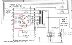
The simple circuit circled in red in the pic supplies +/-14v to the opamp based preamp in a Kenwood KA-4006. It is coming directly off the main rectifiers at +/-34v
Will this +/-14v shunt zener supply have ripple? A lot? If so, are there any simple ways to reduce ripple or clean up this supply?
Thanks in advance...
The ripple will be directly proportional to the current and we don't know the current.
For this application I would use a simple three lead regulated like the LM78xx/LM79xx. Or if you need mmore power there are 5 amp versions available.
Starting with 34V means whatever regulatoer you use will have to turn a lot of power into heat. What you might try is using a simple shunt like you have be set it for about 18 volts. Then use the LM78/79 to reduce the remaining 4V.
Thanks for the reply ChrisA
The main rectifier is at 34v. The shunt zeners' Vf is 14v so that leaves 20v to be dropped by the resistors. 20/1000 = .02 So I am thinking that the current is 20mA. Is that right?
I am a newb (guess I should have stated that, lol). I have no idea what a "three lead regulated" is.
The main rectifier is at 34v. The shunt zeners' Vf is 14v so that leaves 20v to be dropped by the resistors. 20/1000 = .02 So I am thinking that the current is 20mA. Is that right?
I am a newb (guess I should have stated that, lol). I have no idea what a "three lead regulated" is.
Hi,
I must be missing something ? the resistors and zeners appear to
be driven directly by the bridge without input smoothing capacitors.
Surely that is wrong ? Adding them would make a big difference.
Edit : Sorry they are there, towards the top right of the diagram.
rgds, sreten.
A three lead regulator is your standard voltage regulator, use 15V types.
Last edited:
@ sreten
Is that not what Ck3, Ck4 are? 470uf/16v caps in parallel with the zeners
Hi, No, its C3 and C4, 6,800uF 50V, that do the pre-smoothing, rgds sreten.
I would expect the maximum ripple to be something like 10mV pp.Will this +/-14v shunt zener supply have ripple? A lot?
If so, are there any simple ways to reduce ripple or clean up this supply?
Yes, you could split the 1K resistors into two 470 ohm, and displace the 470µF to the mid-point. The ripple would become ~0.7mV pp.
A small capacitor across the zener might still be required for the circuit to function properly.
Elvee @ #8,
thats very good advice. The 470uF capacitor forms an RC filter. As built the R is 1k in parallel with the zener impedance, which at 20mA will be pretty low - 10s of Ohms. So although it might look like a 1/(2*pi*1k*470uF) = 0.34Hz low-pass filter that ought to reduce 100/120Hz ripple by ~ 50dB, in reality its more like a 34Hz LPF, so only provides about 10dB reduction in ripple.
putting the 470uF cap in the middle of the 1k resistor maximises the resistance seen by the cap. at power-up the zener isnt conducting and R = 470R. Once the zener starts conducting then R = 470R//(470R + Rzener) so R ~ 235R. then Fc = 1.44Hz and you get ~ 37dB ripple reduction.
The Zener limited supply works. But you can do a lot better.
Splitting the resistor in two and adding an extra cap converts the RC supply to an RCRC supply.
This improved supply could then feed the Zener or a 3PIN regulator or a discrete regulator.
You have many choices including leaving it as is.
Splitting the resistor in two and adding an extra cap converts the RC supply to an RCRC supply.
This improved supply could then feed the Zener or a 3PIN regulator or a discrete regulator.
You have many choices including leaving it as is.
...The 470uF capacitor forms an RC filter. As built the R is 1k in parallel with the zener impedance, which at 20mA will be pretty low - 10s of Ohms. So although it might look like a 1/(2*pi*1k*470uF) = 0.34Hz low-pass filter that ought to reduce 100/120Hz ripple by ~ 50dB, in reality its more like a 34Hz LPF, so only provides about 10dB reduction in ripple.
Terry,
But doesn't the ~10 Ohm Zener resistance and the 1K series resistance already form a 1/100 divider.
Hope this helps
-Antonio
Yes.
Moving the cap to a 'centre tap' on the resistor would improve smoothing, by putting two hum attenuators in cascade, but you would still need a cap across the zener to get rid of zener noise and ensure a low AC impedance there to prevent supply rail feedback in whatever circuit it is feeding.
Moving the cap to a 'centre tap' on the resistor would improve smoothing, by putting two hum attenuators in cascade, but you would still need a cap across the zener to get rid of zener noise and ensure a low AC impedance there to prevent supply rail feedback in whatever circuit it is feeding.
magnoman, yes it does. and thats what limits the ripple rejection without a cap.
If however one does as I once did, and thinks "hey, I want a whole bunch more ripple rejection" then adds the cap (and casually ignores the zener resistance), one does not get an extra 50dB of attenuation, one gets an extra 10dB (ish).
[in my case I noticed the measured ripple was >> the calculated ripple and then spotted the rather silly mistake in my calc. I was very interested in reducing LF ripple but unconcerned about zener noise so went for the R-C-R-Z approach, which allowed me to use a much smaller cap for the desired ripple rejection]
Hum?

Elvee I agree with you but I have a similar arrangement in my ancient TEAC BX300 and the hum is undetectable as the preamp uses 4x4558N i.c. and the current is virtually negligible(about 20mA per channel) The ripple rejection is about 60dB if I remember correctly. What did make a huge difference in the power amp was to increase the main caps to 100 000uF on each power "busbar" This amp had this desease that it trips the protection circuit if I was running it at full power as a public address unit. I was asked to do this as the amp that was needed blew up during a "Family Life" conference.At relatively high current levels like here, the zener noise will be tiny compared with the 700µV residual ripple, and anyway, there is almost certainly a local decoupling at the point of load.
Thanks a lot everyone Good ideas and I have spent the past day getting up to speed with some of your suggestions.
@tauro0221 - Yes thank you, the caps will be updated. The PS is the final phase of this (my first big) project. Main amp, phono, and preamp/tone boards have all be redone with some modest mods including OPA2134 to replace JRC4558 in the preamp.
Learning how to feed the OPA2134 properly is the reason I am here now
 Whether there is something to be gained, with reasonable effort, over the existing simple shunt zener set-up.
RCRC filters would be difficult to implement because this is an old Kenwood, not DIY, and there really is no place to add components on the existing PCB. I considered adding a new small PCB but can't see anywhere to put it.
However, adding LM78/79 regulators might be a possibility. If it would work to install them in place of the resistors (Ri27, Ri28) connected to the supply lines where they enter the preamp board. I would have to improvise a connection for the ground legs of the regulators. And I would likely use the plan suggested by ChrisA of keeping the existing shunt zener circuit intact, but change to 18v zeners to drop most of the voltage, reducing heat dissipation in the regulators.
Questions:
Would removing these resistors (Ri27, Ri28) disable an existing RC filter?
In this application, would adding the regulators yield noticeable sonic improvement vs the original shunt zeners alone??
Would there be any negatives? Any way in which the original circuit might be better?
.
Good ideas and I have spent the past day getting up to speed with some of your suggestions.@tauro0221 - Yes thank you, the caps will be updated. The PS is the final phase of this (my first big) project. Main amp, phono, and preamp/tone boards have all be redone with some modest mods including OPA2134 to replace JRC4558 in the preamp.
Learning how to feed the OPA2134 properly is the reason I am here now
Whether there is something to be gained, with reasonable effort, over the existing simple shunt zener set-up.RCRC filters would be difficult to implement because this is an old Kenwood, not DIY, and there really is no place to add components on the existing PCB. I considered adding a new small PCB but can't see anywhere to put it.
However, adding LM78/79 regulators might be a possibility. If it would work to install them in place of the resistors (Ri27, Ri28) connected to the supply lines where they enter the preamp board. I would have to improvise a connection for the ground legs of the regulators. And I would likely use the plan suggested by ChrisA of keeping the existing shunt zener circuit intact, but change to 18v zeners to drop most of the voltage, reducing heat dissipation in the regulators.
Questions:
Would removing these resistors (Ri27, Ri28) disable an existing RC filter?
In this application, would adding the regulators yield noticeable sonic improvement vs the original shunt zeners alone??
Would there be any negatives? Any way in which the original circuit might be better?
.
Attachments
Last edited:
Thanks a lot everyone
@tauro0221 - Yes thank you, the caps will be updated. The PS is the final phase of this (my first big) project. Main amp, phono, and preamp/tone boards have all be redone with some modest mods including OPA2134 to replace JRC4558 in the preamp.
Learning how to feed the OPA2134 properly is the reason I am here now
RCRC filters would be difficult to implement because this is an old Kenwood, not DIY, and there really is no place to add components on the existing PCB. I considered adding a new small PCB but can't see anywhere to put it.
However, adding LM78/79 regulators might be a possibility. If it would work to install them in place of the resistors (Ri27, Ri28) connected to the supply lines where they enter the preamp board. I would have to improvise a connection for the ground legs of the regulators. And I would likely use the plan suggested by ChrisA of keeping the existing shunt zener circuit intact, but change to 18v zeners to drop most of the voltage, reducing heat dissipation in the regulators.
Questions:
Would removing these resistors (Ri27, Ri28) disable an existing RC filter?
In this application, would adding the regulators yield noticeable sonic improvement vs the original shunt zeners alone??
Would there be any negatives? Any way in which the original circuit might be better?
.
those resistors are power supply decoupling, or local rc filter, better to leave them alone...
if you are not having issues with your existing amp, it is better to leave it be...
now if you are asking so that you will have ideas in your upcoming diy, then by all means you are welcome to experiment......
you can do a lot of so called tweaks but they will probably sound good to your ears alone, the joy of being able to build something with your hands is immeasurable..........you are welcome to try..........
making modifications without knowing what the likely outcome is, could result in a fatally damaged amplifier.
Excellent advice AndrewT. But excellent advice is typical for you
Yes, I read many threads here at DIY because I believe there is much to learn from digging through past conversations. I have noted that many times yours is the voice of reason in a sea of chaos. Please do not assume that I am on the path of making rash decisions that will cause damage. I am very methodical and thorough in my approach to learning. And my physical work (soldering etc) is meticulous. BUT... everyone has to start somewhere. I am here seeking advice and opinions of those (many) of you who are more knowledgeable than myself.
So, I would like to know the likely outcome of the mod I mentioned in my last post. What is your opinion? (assuming that it would be implemented correctly)
those resistors are power supply decoupling, or local rc filter, better to leave them alone...
Thanks for your input Tony. Those resistors on the tone board have been changed from original and will likely be changed again, if not eliminated.
Why? The new opamp draws more current than the original. The original JRC4558 was operating at +/-9v (the PS +/-14 being dropped by Ri27 and Ri28). But the new OPA2134 pulls more current hence more IR drop through the resistors. It is operating at around 7v when the 680R resistors are in place.
Is it ideal to operate the OPA2134 at +/-7v? Am I supposed to go back to the 4558 when the 2134 sounds so much better?
I temporarily have 56R resistors in place of the 680R to give the OPA2134 more voltage. No negative impact from this change that I can observe. This is a process of experimentation and learning...
if you are not having issues with your existing amp, it is better to leave it be...
now if you are asking so that you will have ideas in your upcoming diy, then by all means you are welcome to experiment......
Having issues with my amp? I bought this amp, not working, for $15 specifically so that I could learn by repairing it ( done- replaced outputs) recapping it ( done- except for the PS) and modding it in any reasonable way that would actually yield sonic benefits. I believe that this is what DIY is about.
you can do a lot of so called tweaks but they will probably sound good to your ears alone, the joy of being able to build something with your hands is immeasurable..........you are welcome to try..........
I may be still on the noob end of the spectrum here. But would implementing a regulated PS for the preamp be considered just a tweak?
I understand that the preamp PS is already regulated by the zeners. But wouldn't a voltage regulator be a step up? I have looked at amp schematics. What I have seen is that BOTL amps use the simple shunt zener regulation like I have here. And as you move up the pecking order better methods are employed for voltage regulation, ESPECIALLY for the preamp. Am I wrong?
I appears to me that I may have an opportunity to make an improvement.
Something needs to be done with the preamp PS anyway because I suspect that it was marginal as originally designed. It can deliver only 20mA before coming out of regulation. This PS supplies both the phono board and the preamp/tone board. With 4558's in place (as original) the combined draw of these boards, at idle, is around 11mA which leaves only 9mA in reserve.This seems marginal to me. Someone tell me please...is this cutting it close or not?
But then the new opamp in the preamp draws more current than the original: 4mA more at idle. This leaves only about 5mA in reserve. Same question as above - if I run this way will the preamp PS be coming out of regulation?
Come on all you good DIY guys...
- Status
- This old topic is closed. If you want to reopen this topic, contact a moderator using the "Report Post" button.
- Home
- Amplifiers
- Power Supplies
- Questions re: ripple in this simple shunt zener PS