Hi Everyone,
I have designed and built a basic power supply for a speaker system project of mine but am having trouble in finding the cause of this problem.
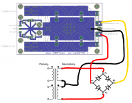
It is set up as most PSU's are as a dual polarity supply, but with the main power rails (around +/-35V from a 25V dual secondary transformer) regulated down to +/-15V (using L78/7915 regs) for the input circuitry. There are also dropper resistors to reduce the voltage going to the regulators to something that is in their input voltage range.
The positive reg works fine, regulating whatever voltage is input into it down to +15V all the time, whilst the negative regulator will only drop some of the voltage (say 35V down to only around 23V), regardless of whether the input voltage is in or out of its range.
For example, I connect the board up to my lab supply and raise the voltage up past +/-15V to something that is comfortably in the range of the input voltage of the regulators. The positive reg does its job and drops it down to +15V whilst the negative reg never produces -15V, and its output voltage only rises when the main rail voltage rises.
I have checked the layout and there is nothing wrong there, and all the regs have bypass capacitors right next to them, so I am wondering what is wrong.
Below I have uploaded a (very much) simplified version of how everything is connected.
I have designed and built a basic power supply for a speaker system project of mine but am having trouble in finding the cause of this problem.
It is set up as most PSU's are as a dual polarity supply, but with the main power rails (around +/-35V from a 25V dual secondary transformer) regulated down to +/-15V (using L78/7915 regs) for the input circuitry. There are also dropper resistors to reduce the voltage going to the regulators to something that is in their input voltage range.
The positive reg works fine, regulating whatever voltage is input into it down to +15V all the time, whilst the negative regulator will only drop some of the voltage (say 35V down to only around 23V), regardless of whether the input voltage is in or out of its range.
For example, I connect the board up to my lab supply and raise the voltage up past +/-15V to something that is comfortably in the range of the input voltage of the regulators. The positive reg does its job and drops it down to +15V whilst the negative reg never produces -15V, and its output voltage only rises when the main rail voltage rises.
I have checked the layout and there is nothing wrong there, and all the regs have bypass capacitors right next to them, so I am wondering what is wrong.
Below I have uploaded a (very much) simplified version of how everything is connected.
Attachments
Most monolithic voltage regulators have their regulation characteristics specified between a min and max current.
In this case, the min current is 5mA, which means that below this value the regulation is unspecified.
It doesn't mean all regulators will cease to function below 5mA, but some might, and the 79xx series is more prone to problems at high input voltages and/or low loads than others.
The solution is to use a bleeding resistor <3K at the output.
BTW, using dropping resistors at the input is a very bad idea: they will not reduce the input voltage at low currents, and regulators hate seeing a high impedance at their input. It is an excellent recipe for troubles, like unwanted oscillations.
Maybe you have killed the 7915 with overvoltage? Datasheet lists -35V as absolute maximum for 7915, which means -36V even for a fraction of a second might cause permament damage, even at no current through chip. If you have left the PSU unloaded, the resistor doesn't drop voltage for chip (Voltage over resistor is current times resistance, so at I = 0A U = 0V). Also some trafos give a bit higher than rated voltage when unloaded, 10 % is not uncommon but well enough to push regulator over limit (resistance of wiring eats some voltage, due to same law of U = I * R, voltage rating is often given with rated load). A bit unrelated, but 20mF of filtering capacitance also seems awful high: assuming you're running off 50Hz mains, you get unregulated peak voltage once every 10 ms (twice per cycle). As dU = I/C, assuming I is maximum rated to 7yxx (1,5A) capacitors are going have voltage drop of dU * dt = I/C * dt = (1,5A / 20mF) * 10ms = 0,75 V. While low voltage ripple has obviously been a design goal, having huge input filter capacitors isn't the way to go with it: As an exercise left to reader, calculate how long (in milliseconds) sine wave-formed voltage of transformer is within top 0,75V of cycle, and assuming constant current throughout that period, calculate current going through transformer into capacitors (hint: you can use time current is coming from capacitors and compare that to time current is coming). To get better regulation of voltage, maybe you could consider cascading regulators (21V feeding 15V), but I've never used cascaded regulation so don't take my word for it.
It is better to add a zener in each input of the regulator, of a slowly higher voltage than the minimum needed to overcome the drop out of it, say 5-6V over output voltages of each regulator. Or use HV versions of some regulators available, LM317 has a HV version (60V max input).
Thanks for all the advice, will definitely try loading the outputs before measuring the voltage this time.
As for killing the reg, I replaced it once, and then increased the voltage on my lab supply below the maximum input voltage for the regulator (the supply only goes up to 30V) and still, it did not regulate.
Therefore, I am thinking that it is purely to do with the loading of the outputs. I also agree about the high input impedance-although it probably wouldn't cause too much oscillation with the bypass caps being so close, I understand that it is not a good thing for power supplies. At least I have space on the board (where the dropper resistors are) to add a zener if I need to go down that route.
Hi Everyone,
I have designed and built a basic power supply for a speaker system project of mine but am having trouble in finding the cause of this problem.
It is set up as most PSU's are as a dual polarity supply, but with the main power rails (around +/-35V from a 25V dual secondary transformer) regulated down to +/-15V (using L78/7915 regs) for the input circuitry. There are also dropper resistors to reduce the voltage going to the regulators to something that is in their input voltage range.
This is going to be very unreliable. +/- 35 volts to simply to high for a 78xx or 79xx regulator. Your dropping resisters are useless until you have a load going.
What you need is a transistor, rated for at least 50V and use the LM79/78 to control the base of the pass transistor. Look in the data LM78/79 data sheets for an example
Remember about "transients" and start up and shut down. Put in some zeniers to shunt over voltage around the pass transistor.
There was a load on the circuit, but it was the ~5mA quiescent current through the regulators. At that minimum current, you'd want the series resistors to be >200 ohms (for >1V drop). But I'd do without them. 25V (transformer secondary) times 1.414 equals 35.35 volts. With bridge diode drops you should be under the 35V max reg input. It's close so I would definitely measure to see exactly where it's at. The circuit should otherwise be good for about 100mA with only the smallest of heat sinks (20V x 100mA = 2W). For your average input circuitry that should be plenty.
There was a load on the circuit, but it was the ~5mA quiescent current through the regulators. At that minimum current, you'd want the series resistors to be >200 ohms (for >1V drop). But I'd do without them. 25V (transformer secondary) times 1.414 equals 35.35 volts. With bridge diode drops you should be under the 35V max reg input. It's close so I would definitely measure to see exactly where it's at. The circuit should otherwise be good for about 100mA with only the smallest of heat sinks (20V x 100mA = 2W). For your average input circuitry that should be plenty.
Exactly what I thought when designing the supply. I did know that it was going to be close without the dropper resistors, and that is why I included them. I'm not sure what value I calculated now, but it was quite high. I did over-estimate current though, so I may need to raise the value a bit higher again.
To ChrisA, the load will be there all the time, from when the supply is turned on until after it is turned off. So the dropper resistors will work since the load is pretty constant and is always above the minimum load for the regulators.
One option would be to use 2-stage regulation. That would provide for 40V input and less voltage drop, ie power dissipation, per device. At a minimum benefit.
No disrespect intended, just stating it bluntly... the 3-terminal fixed regs need only a proper input voltage to work, so most all problems are not the regulator. You should visually follow the current flow on your board/schematic.
No disrespect intended, just stating it bluntly... the 3-terminal fixed regs need only a proper input voltage to work, so most all problems are not the regulator. You should visually follow the current flow on your board/schematic.
Thanks for the advice sofaspud, sorry if it didn't sound like it, but I was actually agreeing with you in the first place!
I will probably end up trying loading the outputs with a resistor first, and then keeping it there when everything is finished, to save damaging the pre circuitry. It would also help load the dropper resistors enough, so they drop the voltage to what they should be (as calculated).
I will probably end up trying loading the outputs with a resistor first, and then keeping it there when everything is finished, to save damaging the pre circuitry. It would also help load the dropper resistors enough, so they drop the voltage to what they should be (as calculated).
precede the regulator with an rCRC PSU.
You currently have an rC PSU. The r = series resistance in the transformer and rectifier circuits.
The C is the first capacitor bank.
The added R & C improve the rejection of mains transients and attenuation of hum and it's harmonics.
Try 100r for the added R and add on a second bank of the same capacitors as you have at present for the second C.
This style of PSU (rCRC or rCLC) is very good for almost all circuits that need DC from the mains.
Once, again, thanks for the advice, but since I have already built the boards and they are pretty much set up and ready in the box, I won't be able to modify them. I am happy with what I've done for now, but will be including all the advice people have given me into designing power supplies in future projects.
It turned out that the regulator was not doing its job because I was measuring without any load on the output. This was solved by putting a 1k resistor across the output and ground. At 15V this gives about 15ma of current draw and about 0.2 watts of dissipation in the resistor-fine to use a standard 0.25W resistor.
It turned out that the regulator was not doing its job because I was measuring without any load on the output. This was solved by putting a 1k resistor across the output and ground. At 15V this gives about 15ma of current draw and about 0.2 watts of dissipation in the resistor-fine to use a standard 0.25W resistor.
For long term non critical use I would suggest Pq ~ 25% of Pmax.
For critical use Pq < 10% of Pmax.
Since you have the load circuit permanently connected, you can increase the 1k0 (bleed resistor) to a higher value. Try 2k2 or 3k3. You could add a LED in series with this resistor as a Power ON indicator.
For critical use Pq < 10% of Pmax.
Since you have the load circuit permanently connected, you can increase the 1k0 (bleed resistor) to a higher value. Try 2k2 or 3k3. You could add a LED in series with this resistor as a Power ON indicator.
regulation
I had a similar problem and the WATTAGE that the I.C.s can handle was exceeded if you use the "T" version i.e. the top66 IS ONLY FIFTEEN(15) WATTS . Maybe use a "bypass" transistor to handle the bulk of the current as I think that the internal power limiting is exceeded and then they behave very odd.
Hi Guys and DollsHi Everyone,
I have designed and built a basic power supply for a speaker system project of mine but am having trouble in finding the cause of this problem.
It is set up as most PSU's are as a dual polarity supply, but with the main power rails (around +/-35V from a 25V dual secondary transformer) regulated down to +/-15V (using L78/7915 regs) for the input circuitry. There are also dropper resistors to reduce the voltage going to the regulators to something that is in their input voltage range.
The positive reg works fine, regulating whatever voltage is input into it down to +15V all the time, whilst the negative regulator will only drop some of the voltage (say 35V down to only around 23V), regardless of whether the input voltage is in or out of its range.
For example, I connect the board up to my lab supply and raise the voltage up past +/-15V to something that is comfortably in the range of the input voltage of the regulators. The positive reg does its job and drops it down to +15V whilst the negative reg never produces -15V, and its output voltage only rises when the main rail voltage rises.
I have checked the layout and there is nothing wrong there, and all the regs have bypass capacitors right next to them, so I am wondering what is wrong.
Below I have uploaded a (very much) simplified version of how everything is connected.
I had a similar problem and the WATTAGE that the I.C.s can handle was exceeded if you use the "T" version i.e. the top66 IS ONLY FIFTEEN(15) WATTS . Maybe use a "bypass" transistor to handle the bulk of the current as I think that the internal power limiting is exceeded and then they behave very odd.
Half wave rectification does not reduce the voltage, except for the small drop increase in the components caused by increased current stress.Use half wave recifier to reduce the input voltages.
- Status
- This old topic is closed. If you want to reopen this topic, contact a moderator using the "Report Post" button.
- Home
- Amplifiers
- Power Supplies
- Power Supply Voltage Regulator Problem