Quite a while back Fred Dieckmann illustrated a fixture for testing power supply regulators and it can be employed to measure the impedance of your supply.
The MOSFET is biased into Class-A so must be heat sinked.
An externally hosted image should be here but it was not working when we last tested it.
The MOSFET is biased into Class-A so must be heat sinked.
Thanks again.
The power transformer is rated at 230V, when loaded it is around 200V. Secondary windings DC resistance is 220 ohms per winding.
Chokes' DC resistance is 90 ohms for both.
The chain of 390 ohms resistors, it draws about another 70mA.
If you wonder why the resistor chain is wasting so much current, I did this to cut down the supply voltage. If you wonder why I didn't cut voltage the usual way (putting them in series with the chokes), I observed a noticeable improvement in bass when comparing between the 2. I thought it interesting, and this made me look into the effect of Zout of PSU. But this also keep the load DC resistance low, so I plan to get rid of it.
Of course in theory I should just dump the power transformer, replace it with one with appropriate rating, and do without the resistors. but that cost money.
So total current draw is around 140mA, at 110V, it would be about 786 ohms overall.
so are you saying you have a traffo with 230-0-230 secondary?
since you have a choke input filter, raw B+ is around 200vdc....you need to lose 90volts..
to cut down on voltage, you can put additional RC in the B+ line......it will be more effective that way in bringing ripple voltage down....
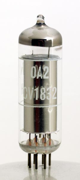
you can also use an 0A2 to shunt regulate the B+.....
you can use higher valued resistors to bias your filament with dc voltage, say 270k to B+ and 82k to ground.....the junction connects to 2 470ohm resistors to each leg of the filament supply....this ensures that current drain is low...
do not dump your traffo just as yet....resistors are cheaper.....

so are you saying you have a traffo with 230-0-230 secondary?
Something like that, specifically I used 2 traffos with 230V secondary)
since you have a choke input filter, raw B+ is around 200vdc....you need to lose 90volts..
to cut down on voltage, you can put additional RC in the B+ line......it will be more effective that way in bringing ripple voltage down....
I did tried that before I got to this. A lot of series resistance audibly affected the bass. The bass has that rounded sound. By switching to this arrangement, bass sounded "normal" again. This led me to investigate about this.
you can also use an 0A2 to shunt regulate the B+.....
I didn't know something like this existed. I tried looking for a schematic on how to use it, no luck so far. Does it work like a Zener diode?
you can use higher valued resistors to bias your filament with dc voltage, say 270k to B+ and 82k to ground.....the junction connects to 2 470ohm resistors to each leg of the filament supply....this ensures that current drain is low...
Yes that is the "normal" way, I was just trying to kill 2 birds with 1 stone.
do not dump your traffo just as yet....resistors are cheaper.....
True.
But I kinda went another way. I intend to use another tube (EL84), its operating point is more suited to my traffo, still waiting for the parts to come.Quite a while back Fred Dieckmann illustrated a fixture for testing power supply regulators and it can be employed to measure the impedance of your supply.
An externally hosted image should be here but it was not working when we last tested it.
The MOSFET is biased into Class-A so must be heat sinked.
Thanks.
That looked like a handy tool. Unfortunately most things SS are a bit beyond me at the moment. I see you have a choke input supply. The formula I gave you was for a cap input supply. For a choke input supply it is much simpler: provided that you are taking enough current the effective DC resistance of the supply is just R's plus choke resistance etc. No factor of 5 (i.e. duty cycle) in front of R's, and the 0.005/C term disappears because the cap is being continuously charged.
The effective 40Hz impedance of the last capacitor in the PSU is given as above by the formula
Z = 1 / 2 / Pi / Freq / C
for 1mF//120uF the C=0.00112F
Freq is stated as 40Hz.
Pi ~ 3.142
Z ~ 3.6ohms.
That is ~ 1/22 of the load resistance value. Well below 1/10 stated above.
All the other factors are just small corrections to that 3.6ohms calculated. eg, esr raises it slightly. Preceding Capacitance lowers it slightly. Transformer impedance is probably not relevant.
I see you have a choke input supply. The formula I gave you was for a cap input supply. For a choke input supply it is much simpler: provided that you are taking enough current the effective DC resistance of the supply is just R's plus choke resistance etc. No factor of 5 (i.e. duty cycle) in front of R's, and the 0.005/C term disappears because the cap is being continuously charged.
Thanks. Does DC damping factor matter in this case?
The effective 40Hz impedance of the last capacitor in the PSU is given as above by the formula
Z = 1 / 2 / Pi / Freq / C
for 1mF//120uF the C=0.00112F
Freq is stated as 40Hz.
Pi ~ 3.142
Z ~ 3.6ohms.
That is ~ 1/22 of the load resistance value. Well below 1/10 stated above.
All the other factors are just small corrections to that 3.6ohms calculated. eg, esr raises it slightly. Preceding Capacitance lowers it slightly. Transformer impedance is probably not relevant.
So it all boils down the the size of the last cap? And shouldn't amplifier's current draw somehow be factored in?
Not sure what you mean. Damping factor is an AC concept.Navyblue said:Does DC damping factor matter in this case?
Not sure what you mean. Damping factor is an AC concept.
Really?
I mean does R's + choke resistance need to be below a certain level with respect to the load resistance?
let us look at your scheme again....
excluding filament power, let us find out your plate power needs, 2 x 6H30 tubes operated at 110v plate at 30mA is 6.6 watts, the bleeders which is 4 x 390ohms is 7.7 watts.......total current draw is 130mA......accross 2 chokes with combined resistance of 180ohms is another 3 watts...so total wattage required equals 17watts, so any power traffo that can supply more than 17 watts is a go.......
what is the voltage wanted at the input choke? 110 volts plus 23.4volts or 133.4 volts.....
perhaps just 1 traffo with a fwb would have been sufficient....
working with tubes, you will find out that voltages calculated seldom jibe exactly with actual..... unloaded voltages drops big under load and this is due to the resistance in the secondary winding.....
how big is your traffo anyway? i am interested in the center leg and stacking dimensions....
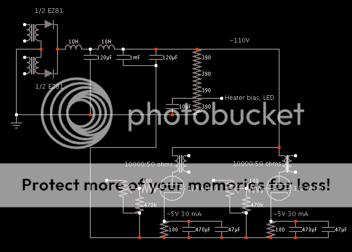
I didn't know something like this existed. I tried looking for a schematic on how to use it, no luck so far. Does it work like a Zener diode?
the 0A2.........yes, you can say it is like a zener diode in function.......0A2 @ The National Valve Museum
perhaps just 1 traffo with a fwb would have been sufficient....
...
how big is your traffo anyway? i am interested in the center leg and stacking dimensions....
Please pardon me.
What is "fwb"?
And what are centre leg and stacking dimension?
Btw the traffo 2 pieces of 12VA 230V (0-115-230V) to 230V (0-110-230V), used as 230-0-230V.
Please pardon me.
What is "fwb"?
And what are centre leg and stacking dimension?
Btw the traffo 2 pieces of 12VA 230V (0-115-230V) to 230V (0-110-230V), used as 230-0-230V.
fwb is full wave bridge......you can also parallel 2 secondaries, 230volt ac rectified gives you around 220volts dc to the input choke....
so you are using small traffos......that explains a lot of things....
Thanks Jan.
So, we can completely ignore it? In my case, my transformer's secondary DC resistance is 220 ohms, and my DC load is under 1k ohms. If I plug the numbers into the formula I can't even hit 1:1 ratio let alone 1:10.
Remember that your transformer is disconnected from the supply for 80% of the time. Only during the short period that the secondary voltage is above the cap voltage do the diodes open and top up the cap. The sec DC resistance does figure in how fast the cap can be replenished and that determines the mains ripple on the cap.
So it's a bit confusing to talk about the 'power supply DC resistance' - there is no single number for that.
jan
looks like navyblue has been reading the wrong stuff.....
these are recommended readings.....
http://www.diyaudio.com/forums/tubes-valves/67502-seeking-all-norman-h-crowhurst-papers.html
Tube Literature
these are recommended readings.....
http://www.diyaudio.com/forums/tubes-valves/67502-seeking-all-norman-h-crowhurst-papers.html
Tube Literature
He is using choke input, so the transformer is connected for almost all of the cycle.janneman said:Remember that your transformer is disconnected from the supply for 80% of the time.
It depends on whether AC or DC impedance is being considered. The last capacitor usually sets AC impedance, except near a PSU LC resonance. The DC impedance includes a term from the transformer secondary effective resistance, but this is multiplied by a duty cycle figure which will be 1 for choke input and perhaps 5 for cap input.
Thank you all again for all your inputs.
I simply picked one that is big enough, then I realises that the secondary resistance is much higher than a bigger one that I used previously. So what happens if I use small traffos?so you are using small traffos......that explains a lot of things....
That's true. I have been looking to find info on this subject and has been googling rather indiscriminately, and I don't know the context of what I am reading.looks like navyblue has been reading the wrong stuff.....
these are recommended readings.....
http://www.diyaudio.com/forums/tubes-valves/67502-seeking-all-norman-h-crowhurst-papers.html
Tube Literature
- Status
- This old topic is closed. If you want to reopen this topic, contact a moderator using the "Report Post" button.
- Home
- Amplifiers
- Power Supplies
- Unregulated power supply output impedance