See this, especially Figure 2. Note that the transformer CT goes to one end of the caps ground connection, and the amp/speaker return/chassis grounds all go to the other end.
Funny, the schematical representation in fig 3.2-4 and the connection in between the caps in the drawing look the same to me: a star. If this is a copper rod, then the resistance from end to end is very very small (my guess < 0.5-1 milliOhm) and cannot be considered a bussed ground. If these are terminals that are screwed down to it, the contact resistances might be higher than the resistance of the rod.
What the author meant with "bussed ground" is more like long traces between the several different caps in the PSU filter, resembling e.g. the long power supply strips of a breadboard. This is most likely what OP is suffering from and hence my request to retry the PSU built according to fig 3.2-4.
To my mind we were talking about the same thing, but calling it different names.
I'm guessing the drawing is a hardwired setup, but if you were to place the caps on a pcb, a large copper area in the same place between the caps would act the same.
Attachments
OK, so you don't understand the basics of grounding. Two rules: every connection has resistance so will drop some voltage so make sure this happens in the right place; every grounded point must have one and only one connection to every other grounded point so no loops.jitter said:Funny, the schematical representation in fig 3.2-4 and the connection in between the caps in the drawing look the same to me: a star.
It is a bus because it is not of zero size and zero resistance. The resistance is small, but 1 milliohm is a lot if you have, say, 10A peak charging pulses. In fact, every star is really a small bus. The trick with grounding is to ensure that these 10mV (or whatever) signals appear where they can do no harm. His wiring is correct: the dirty stuff is at the CT end and then he grounds the clean end at the other end of the copper.If this is a copper rod, then the resistance from end to end is very very small (my guess < 0.5-1 milliOhm) and cannot be considered a bussed ground.
Thanks everyone, I didn't have time last night, but will definitely rebuild the supply tonight w/ careful attention to grounding. This has all been very informative. I know everything flows down the path of least resistance, but never thought about how literal that is in practice.
I'm actually starting to wonder how my couple of point to point amps I built from scratch are successful! I guess I did build those w/ careful attention to grounding, unlike this breadboard power supply.
I'm actually starting to wonder how my couple of point to point amps I built from scratch are successful! I guess I did build those w/ careful attention to grounding, unlike this breadboard power supply.
Alright, I rebuilt it. It's quiet. It's still on breadboard, so I couldn't exactly do a star, but did bus.. grounded everything along the conductor going down one edge of the board. CT in the first hole, cap in the 2nd, regulator grounds in the next few, and finally the connection to the synth.
Now I've discovered a problem w/ my home electric. When the AC goes on the power drops about 10v which doesn't leave enough for my 12v regulator! I should have gotten a 2x15v transformer, rather than the 2x12 I've got. (Or 200 amp service to my house )
Thanks DF96, and everyone else too.
Now I've discovered a problem w/ my home electric. When the AC goes on the power drops about 10v which doesn't leave enough for my 12v regulator! I should have gotten a 2x15v transformer, rather than the 2x12 I've got. (Or 200 amp service to my house )
Thanks DF96, and everyone else too.
Last edited:
Alright, I rebuilt it. It's quiet. It's still on breadboard, so I couldn't exactly do a star, but did bus.. grounded everything along the conductor going down one edge of the board. CT in the first hole, cap in the 2nd, regulator grounds in the next few, and finally the connection to the synth.
Good to know! Does it make any difference if you unplug the CT and plug it in the hole next to the synth-connection?
Now I've discovered a problem w/ my home electric. When the AC goes on the power drops about 10v which doesn't leave enough for my 12v regulator! I should have gotten a 2x15v transformer, rather than the 2x12 I've got. (Or 200 amp service to my house )
If you use Schottky diodes in the rectifier instead of normal silicon diodes, you might get away with using the 12 V transformer. These diodes have a lower forward voltage drop that might just leave you enough juice to keep the regulators happy.
OK, so you don't understand the basics of grounding. Two rules: every connection has resistance so will drop some voltage so make sure this happens in the right place; every grounded point must have one and only one connection to every other grounded point so no loops.
It is a bus because it is not of zero size and zero resistance. The resistance is small, but 1 milliohm is a lot if you have, say, 10A peak charging pulses. In fact, every star is really a small bus. The trick with grounding is to ensure that these 10mV (or whatever) signals appear where they can do no harm. His wiring is correct: the dirty stuff is at the CT end and then he grounds the clean end at the other end of the copper.
Thanks for clearing things up.
I had a look at the layout of the PSU board of one of our customers and noticed a similar setup as advised by you. The CTs are connected to one side of the board (along with the AC voltages), more or less in the middle are the caps and on the other end the power supply common leaves the pcb (along with the DC voltages). Grounding is taken care of by one big groundplane on the bottom of the board.
His wiring is correct: the dirty stuff is at the CT end and then he grounds the clean end at the other end of the copper.
I don't see why the caps are connected to all four corners in the second diagram, if that's a bus. If it's a star, then I don't see the difference between it and the first diagram.
It is intermediate between a bus and a star. Think of it as a distributed bus. It could easily be a bus, if the copper were more narrow. As in all grounding, think about where the currents flow. In this case you have charging pulses between the CT and the left (reservoir) cap grounds, then ripple current from the left cap grounds to the right (smoother) cap grounds, then nice pure DC plus clean signals out of the other end to the circuit and the speakers.
Yet Another way to look at it
I came across this thread trying to address a similar problem. Hopefully the attached schematic and simulation results add a little more insight to anyone that may still be following this thread or comes across it.
As I feel demonstrated by the discussion, so many struggle with these concepts (myself included). I feel the basic problem is identifying the parasitics. Star grounds can cause as much problems as they fix if the basics of the problem is not understood. However, I do have some fundamental rules I like to follow.
A shield is not a ground return. Make sure you are not confusing a circuit ground with shielding although a circuit ground can provide shielding (so can the positive rail). Account for your return currents. On the later, if it has a goes outa, it needs a goes inta. This is where I see the fundamental problem lies for this situation.
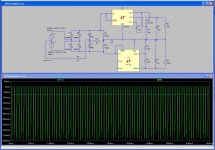
The image of the schematic I have attached includes a parasitic resistance, R9, from the CT of the transformer to the filter capacitors (the xfrm secondary output is represented by two opposed voltage sources V1 and V2). R10 represents the parasitic resistance from the capacitors to the power supply ground. The loads, R8 and R5, hopefully represent the situation that the original poster described. As can be seen by the simulation the unbalanced load causes significant current pulses I(R9) on the CT of the transformer. This is the charging of the filter capacitors. They only charge when the sine wave voltage from the transformer exceeds the diode drops of the rectifier. In addition the difference in the return currents from the outputs of the regulator cause a DC offset current I(R10) on the mutual ground of the two regulator circuits. However, it does not contain the pulsing current because the regulators have effectively filtered it out due to their PSRR and the function of the filter capacitors.
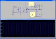
Hopefully this schematic shows that a star ground does not solve the problem if you put the star in the wrong place, like the output of the bipolar power supply. See second schematic. This will induce 8mVp-p of noise on the ground even with just 0.01ohms of parasitic resistance back to the filter capacitors. Connecting it back to the previous circuit but keeping R11 this reduces to below 1uVp-p of ripple on the ground. There is a 1mV DC offset though. Consider this though, a .150” wide 1oz copper trace has ~.001ohms/inch. Ground planes cover a lot of sins.
When the OP built two separate isolated supplies he directly solved his ground current problem. He had a goes outa coupled to its goes inta for EACH supply. With a bipolar supply sharing a command ground the currents add and subtract. You will see the difference and the parasitics are there to show you they exist.
Learned something new.
CFS
I came across this thread trying to address a similar problem. Hopefully the attached schematic and simulation results add a little more insight to anyone that may still be following this thread or comes across it.
As I feel demonstrated by the discussion, so many struggle with these concepts (myself included). I feel the basic problem is identifying the parasitics. Star grounds can cause as much problems as they fix if the basics of the problem is not understood. However, I do have some fundamental rules I like to follow.
A shield is not a ground return. Make sure you are not confusing a circuit ground with shielding although a circuit ground can provide shielding (so can the positive rail). Account for your return currents. On the later, if it has a goes outa, it needs a goes inta. This is where I see the fundamental problem lies for this situation.
The image of the schematic I have attached includes a parasitic resistance, R9, from the CT of the transformer to the filter capacitors (the xfrm secondary output is represented by two opposed voltage sources V1 and V2). R10 represents the parasitic resistance from the capacitors to the power supply ground. The loads, R8 and R5, hopefully represent the situation that the original poster described. As can be seen by the simulation the unbalanced load causes significant current pulses I(R9) on the CT of the transformer. This is the charging of the filter capacitors. They only charge when the sine wave voltage from the transformer exceeds the diode drops of the rectifier. In addition the difference in the return currents from the outputs of the regulator cause a DC offset current I(R10) on the mutual ground of the two regulator circuits. However, it does not contain the pulsing current because the regulators have effectively filtered it out due to their PSRR and the function of the filter capacitors.
Hopefully this schematic shows that a star ground does not solve the problem if you put the star in the wrong place, like the output of the bipolar power supply. See second schematic. This will induce 8mVp-p of noise on the ground even with just 0.01ohms of parasitic resistance back to the filter capacitors. Connecting it back to the previous circuit but keeping R11 this reduces to below 1uVp-p of ripple on the ground. There is a 1mV DC offset though. Consider this though, a .150” wide 1oz copper trace has ~.001ohms/inch. Ground planes cover a lot of sins.
When the OP built two separate isolated supplies he directly solved his ground current problem. He had a goes outa coupled to its goes inta for EACH supply. With a bipolar supply sharing a command ground the currents add and subtract. You will see the difference and the parasitics are there to show you they exist.
Learned something new.
CFS
Attachments
- Status
- This old topic is closed. If you want to reopen this topic, contact a moderator using the "Report Post" button.
- Home
- Amplifiers
- Power Supplies
- Bipolar Supply, Unbalanced Load