Presently I have 3 Artesyn Power Supplies taken from an old but still working SUN V880 Server that was scraped.
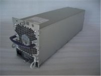
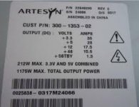
Artesyn Model 22949200, 1175 Watt Power Supply for Sun Fire V880
I actually have what I believe is the complete server and downloaded the manuals for it from the net. Unfortunately the info on the power supplies is quite limited - and definitely no schematic diagrams.
I'm actually chasing service information & schematics just for this power supplies.
My application is to convert them - hopefully - to variable bench power supplies ( for testing big amplifier modules ) of 0-50 volts range for the positive 48 volt rail @ 18+ amps ( or something close ).
I believe the supplies are working fine, but I have no practical documentation on how to hook them up to make them work as a separate module on the workbench.
If you can advise as to where I can source copies of the FULL Power Supply Schematics, it would be greatly appreciated.
Attachments
it's a really cool powersupply. I want it! 
You need to load the +5V line with a power resistor to GND, I recommend 6-10ohm, maybe less.
Then you connect PWR_ON with a on/off switch to GND. I don't know if it'll work on a server powersupply, but it works with common ATX PSU. I have done it once, so search on google for more information about ATX PSU as lab power supply.
I hope that you know the pinouts of the PSU, as it's not standarized compared with ATX PSU.
PWD_ON is something you look after, maybe PWD_OK must also be tied to GND or +5V, or a resistor or a LED+load resistor to GND can be used as a indictor.
Please note that I am not complety sure of PWD_OK in this case.
(a lot of holes to fell in!)
it's a really cool powersupply. I want it!
You need to load the +5V line with a power resistor to GND, I recommend 6-10ohm, maybe less.
Then you connect PWR_ON with a on/off switch to GND. I don't know if it'll work on a server powersupply, but it works with common ATX PSU. I have done it once, so search on google for more information about ATX PSU as lab power supply.
I hope that you know the pinouts of the PSU, as it's not standarized compared with ATX PSU.
PWD_ON is something you look after, maybe PWD_OK must also be tied to GND or +5V, or a resistor or a LED+load resistor to GND can be used as a indictor.
Please note that I am not complety sure of PWD_OK in this case.
(a lot of holes to fell in!)
Thanks for the info. I have stacks of material on Computer ATX PSU units, since I have maybe a good dozen or more my own in boxes ranging from 200 to 400 watts. ( When I scrap an old computer if its useless, I like to hang onto the power components.)
As for the Server PSU, it's output is just under 1200 watts - it has 3 PCBs - 2 large ones and small daughter board. As I can tell the 2 large boards are the output supply rails and filter caps, the other is the main power driver Board and the smaller hard wired daughter board is the control section - ( which looks very analogue in its design and layout - no Micros or PIC devices that i could recognize).
I don't have a picture to place up here - but there is a small section of the Server PS output connector that has about 15-20 small gold pins on it which run to this daughter "control" PCB on the main PSU mother board. The larger main pins are the output supply rails.
( Yes - I could trace the circuit but it will take almost forever to do so - as its surface mount ICs and chip components and I will need my glasses and maybe desolder the board to see the lower extremities of it.) My hunch is this 15-20 pin connector is where it all happens, as they all trace back to this same control PCB, but through the main Switching Power PCB. So its going to be a prick of a job. ( I may have to wreck one good unit to get two working units because of the complexity. )
As these Power supplies are BIG ( 48 volts @18 amps each plus the usual 3.3 /5 /12 volt rails with even more current ). I have 3 of these units.
I want to mount at least 2 units as +/- supplies into a single rack mount cabinet with the 3rd unit as a spare ( as the old cases are rusty ).
They would be good bench supplies for big amplifier testing. I've just got to learn how to activate and mod them for bench work. They run of 240 or 120 volt mains. No moving pots, or switches on the boards - just one big 20 amp ceramic fuse for the mains and around 15 heatsinks throughout.
Fortunately I have the whole server - as a so called working unit when it was pulled from service - And I have all the matching connector plugs for it. I just don't have keys to open the damn doors without buggering the cabinate or locks; and a key is also required to turn the server on ( key-switch ). The unit ran with 3 power cords ( I'd say from 3 phase mains ) but all are single phase power supplies. It takes two strong men to lift the server into the back of my car even though its on castor wheels - so its a big bastard !
Artesyn make these same type of switching supplies up to about 4 KW in size.
Last edited:
I know it's not the elegent solution you're after, but would you considder running the PSU unmodified and fitting a home-made switching regulator on the output? That might be the simplest way to do it. If youre willing to put up with slightly spongey regulation the switching frequency need not be all that high and it should be relatively simple to build.
I know it's not the elegent solution you're after, but would you considder running the PSU unmodified and fitting a home-made switching regulator on the output? That might be the simplest way to do it. If youre willing to put up with slightly spongey regulation the switching frequency need not be all that high and it should be relatively simple to build.
I've thought about that idea even with a linear Reg chip and big bunch of T03 Power transistors, which is easy to do ( in theory ) - but shelving it as a last resort as I don't want it to grow into a real monster.
Thanks for the info. I have stacks of material on Computer ATX PSU units, since I have maybe a good dozen or more my own in boxes ranging from 200 to 400 watts. ( When I scrap an old computer if its useless, I like to hang onto the power components.)
wow, I thought that I was alone (and weird) who collected at powersupplies, I have a box full of SMPS (3-65W), and 4-5 ATX powersupplies stacked up at the floor. (I needed something for 35V/10-20A, I use a 19V/6A laptop powersupply as a temporary solution (CNC-machine, 4.5Ah))
It's a lot of powersupplies on ebay who are easier to connect and use, but where's the fun of it?

( which looks very analogue in its design and layout - no Micros or PIC devices that i could recognize).
hmmm...
Many SMPS laptop PSU have a controller IC (SMD) located on the underside.
Can be an old design, I have a old AT powersupply who have TL494 and LM339 (DIL):
PC Switching Power Supply schematic using TL494/LM339 IC 2003 & KA7500My Electronics Journal
Many powersupplies have one controller, (such as UCC3804N , but the datasheet says that they control only up to 12V), coupled with tranistors/diodes later to split up the power line to 3.3V/5V/12V, so you don't have to look so much at the beginning.
Other have one controller regulated to 12V, then regulate down to 5V and 3.3V from the 12V line, so in practically it may be easier than you think.
I have seen many LM7912 on ATX PSU, if you can find -12V on the output pins it'll be one less pin to worry of.
When life gives you lemons, make lemonade.
have you searched after manual or connection sheme for your PSU?
I have 2 275w server PSU with 70pin connection and I found a connection sheme in the manual, but I haven't fired it up yet.
My hunch is this 15-20 pin connector is where it all happens, as they all trace back to this same control PCB, but through the main Switching Power PCB. So its going to be a prick of a job.
I agree with your hunch, it's not necessary to desolder, but you'll need to look more inside it, get the feeling of it. If you find PWD_ON pin, I feel that you can ignore the main swithing power PCB, but I have too little experience with Server PSU's.
wow, I thought that I was alone (and weird) who collected at powersupplies, I have a box full of SMPS (3-65W), and 4-5 ATX powersupplies stacked up at the floor. (I needed something for 35V/10-20A, I use a 19V/6A laptop powersupply as a temporary solution (CNC-machine, 4.5Ah))
It's a lot of powersupplies on ebay who are easier to connect and use, but where's the fun of it?
hmmm...
Many SMPS laptop PSU have a controller IC (SMD) located on the underside.
Can be an old design, I have a old AT powersupply who have TL494 and LM339 (DIL):
PC Switching Power Supply schematic using TL494/LM339 IC 2003 & KA7500My Electronics Journal
Many powersupplies have one controller, (such as UCC3804N , but the datasheet says that they control only up to 12V), coupled with tranistors/diodes later to split up the power line to 3.3V/5V/12V, so you don't have to look so much at the beginning.
Other have one controller regulated to 12V, then regulate down to 5V and 3.3V from the 12V line, so in practically it may be easier than you think.
I have seen many LM7912 on ATX PSU, if you can find -12V on the output pins it'll be one less pin to worry of.
When life gives you lemons, make lemonade.
have you searched after manual or connection sheme for your PSU?
I have 2 275w server PSU with 70pin connection and I found a connection sheme in the manual, but I haven't fired it up yet.
I agree with your hunch, it's not necessary to desolder, but you'll need to look more inside it, get the feeling of it. If you find PWD_ON pin, I feel that you can ignore the main swithing power PCB, but I have too little experience with Server PSU's.
Totally agree - I know the TL494 & LM339 chips. There will be some sort of controller chip on the board ( unless its made up as a number of other chips ) > I've not had time to de-solder the PCB - yes you'll need a good de-soldering station to work in this as the tracks are hair thin is places.
I'll keep you guys posted as I'm sure you might be interested in this project.
By the way - I've emailed a few of the Companies most like to have such info and their basic reply is -"How many PSU's do you want to purchase ?" - yes they'll sell me a new one in a blink - which is good in so far as you can still buy them without to much difficulty.
I have seen used ones sell on the net for as low as $26 USD and then another $150 to post the box to Australia - as these are not light units for a switch mode.
If I can make one functional it would be worth buying a few, just to have on the shelf for future projects - since big Server supplies are not all that common ( in Oz definitely ). I realize its a luxury few can afford.
Just to give you guys and idea of the complexity of this project - it's nothing like what has been previously mentioned.
The daughter "control" board I spoke of has 28 surface mount IC chips ( an an uncountable number of micro chip parts as well ) within a double sided PCB that I guess is about 6 x 4inches in size - that you can only read information with a magnifier. The tracks that wire them are hair thin, maybe thinner in places.
Additional to that, there is a 48 pin 90 degree header connector joining the daughter and mother PCB's together ( yes the bastard is soldered on ) and the tracks again are hair thin.
Even with my wizz-bang new Xytronics DIA-60 De-soldering Iron ( which went out cheap at "Tricky Dicky" - Dick Smith - a few years ago ) and a new tip, I'm having great trouble just de-soldering the header connector joining the 2 boards because of the through hole plating.
Adding further insult to injury - all the the parts on the daughter PCB are surface mount - which I hate - as I can't see the bloody things without glasses and a magnifier. On the other PCbs you have about 15 large heatsinks scattered about with chip components buried underneath - meaning the heatsinks have the be removed to see the PCB wiring below. ( maybe I've lost the plot on all this and need to get a life !)
The main connector that connects the enclosed power supply module into the server has a small 24 gold pin secondary connector ( using all 24 pins of course ) back into the main server wiring. Having information on this wiring hookup will at least get the bugger to activate on the bench - before any mods can be done.
So the task of just getting the supply fired up on the bench is a challenge in itself.
The up side to all this is - the Manager of one of the US Companies I emailed, has gotten back to say "I need the service documentation" ( dah !!!) which he is looking into chasing for me ( but don't hold your breath waiting for it ! ).
If I can procure this it "might" ( I say "might" - because I'm still not confident its a plug and play setup. ) save, me a lot of grief.
I'm quite concerned de-soldering the PCB's will stuff them once and for all, because linking broken tracks is not realistic in this sort of manufacturing technology.
Anyone got any better Ideas !
( Maybe at the end of the day - I'll just go and buy a big power supply and be done with the hassle ! )
Last edited:
Connector Pinouts - Sun Fire X4600 and Sun Fire X4600 M2 Servers Service Manual
this is pinout for power supply SUN, but newer model then v880. But pin A1 is PS_ON - I think that is it.
this is pinout for power supply SUN, but newer model then v880. But pin A1 is PS_ON - I think that is it.
I just did some reverse engineering on this psu. I took the control pins out of the box using a ribbon cable and measured the voltage levels when the psu was connected to the computer as well as unconnected. Results can be seen here: https://docs.google.com/spreadsheet/pub?key=0AqOeeJ48ZbZ4dDZHWmtOdk5ZclkxNzYybUpIQkVpbUE&output=html
There were two pins that got my attention, #3 and #16 as they seem to get grounded when the power supply is running. So I shorted these pins to the ground, powered the device and voilà!, it came up, steady as hell
It is very well designed and built psu and it can give lots of power to any of its rails, requiring no load to others.. well, at least to my favorite one, 48V rail. I took 260W out of it (I didn't dear to feed more in my 20W resistor) with no problems.
Oh, yes, the ground I believe can be found from pin #15 and the pins closest to the control connector in ports A1 and B1.
I believe this was my first post on this forum! I hope people find this information useful
- Status
- This old topic is closed. If you want to reopen this topic, contact a moderator using the "Report Post" button.
- Home
- Amplifiers
- Power Supplies
- Wanted - Schematic diagrams for Artesyn ( Sun V880 Server ) Power Supplies.