I have a thread going over here: Possibly the most frugal high-end sounding amp? - Page 3
where I've shown a recording of the PSU noise compared to the output signal. My amp gives about 60dB PSRR (with respect to the output) and the PSU noise is about -50dB relative to the output signal. My target is to get this below -60dB wrt the output signal.
Note if you use a more 'mainstream' chipamp (LM3886 being the canonical example), they give PSRR plots relative to the input in the DSs.
http://www.whatsbestforum.com/showt...d-sounding-amp&p=180003&viewfull=1#post180003
I am thinking about having a C-Multiplier for the input stage and the VAS stage. In this way, I should be able to achieve a total of at least -125dB and likely -140dB PSSR from 20Hz up. This shouldn't be too difficult to achieve because the input and VAS stages require only very low current. I think the output stage has inherantly higher PSSR and does not require regulation, not to say that regulation is extremely difficult if possible. (Therefore, it makes no sense to regulate the entire power supply of a class AB amp).
As a matter of fact, I have the above in my mind before I jumped in this thread, as I thought that by "regulating" the front end stages, perhaps having super large capacitance for power amplifiers is unnecessary, because the larger ripples / higher impedance may not cause much harm to the amplifier provided that the PSSR of the front end stages is very high at -140dB. (It will still require low impedance caps to be placed very close to the output device pins, but this is for higher frequencies, not the lower frequencies, therefore the capacitance value need not to be very high).
What do you think? I can be very wrong hence am seeking your ideas.
abraxalito: your "Leaning Tower of Song" is truly amazing.
Last edited:
I've been wondering about output stage PSRR for a while now - on my blog comments I discussed this I think. I tried to simulate a simple emitter follower OPS in LTSpice but found the transistor models provided suck, so gave up with that. Then I went to look at an emitter follower output buffer - LME49600. This shows about 75dB of PSRR but only up to a handful of kHz, its down to 65dB by 20kHz and continues to fall beyond that, faster than 20dB/decade. I'm curious though whether your theory about not needing regulation for the OPS is actually correct - I guess the proof is building both and listening to see if any improvements are evident when regulation is used. What kind of output power are you aiming for? Are you intending a bridged amp?
In my simulation I got possibly 30dB higher PSRR on the output stage comparing to the input and VAS stages hence my above assuptions. But then you reminded me that I cannot be sure about the LMOSFET models I used neither (I guess they might have come from Bob Cordell's models?).
If I assume that the output stage has 65dB PSRR at 20kHz (that is your figure), checking my linear power supply now on +/-85V rails with 10,000uF + 10uH + .022 + 10,000uF + 10uH + .022 + 20,000uF, it has about 40dB PSRR from 1kHz to 100kHz. So the combined PSRR is 105dB at 20Hz. I think that is not bad at all.
Note that this 105dB is at the output after amplification, unlike in the front end before amplification of 30 something dB. So if your 140dB requirement is applied to the front end then the back end only needs about 110dB, and 105dB comes close, depending on the gain of your amplifier.
But then at lower frequencies such as at 20 to 100Hz, the PSRR is worse from perhaps 80dB to 100dB. But I think our ears can accept much higher distortions in these frequencies, so in real life it may not matter.
I noticed that for the back end, for every additional 10,000uF I throw in, I can achieve about 3dB PSSR improvement from 1kHz to 100kHz. Is it worthwhile? I am not so sure.
Last edited:
I am thinking about having a C-Multiplier for the input stage and the VAS stage. In this way, I should be able to achieve a total of at least -125dB and likely -140dB PSSR from 20Hz up. This shouldn't be too difficult to achieve because the input and VAS stages require only very low current. I think the output stage has inherantly higher PSSR and does not require regulation, not to say that regulation is extremely difficult if possible. (Therefore, it makes no sense to regulate the entire power supply of a class AB amp).
As a matter of fact, I have the above in my mind before I jumped in this thread, as I thought that by "regulating" the front end stages, perhaps having super large capacitance for power amplifiers is unnecessary, because the larger ripples / higher impedance may not cause much harm to the amplifier provided that the PSSR of the front end stages is very high at -140dB. (It will still require low impedance caps to be placed very close to the output device pins, but this is for higher frequencies, not the lower frequencies, therefore the capacitance value need not to be very high).
What do you think? I can be very wrong hence am seeking your ideas.
abraxalito: your "Leaning Tower of Song" is truly amazing.
PSRR or not, the primary function of the PSU and decoupling capacitors is to supply the CURRENT demanded, exactly when needed. The current IS the music signal.
There is a minimum total reservoir plus decoupling capacitance that you can not go below, if you expect enough current to be available.
This has been discussed at great length, in this thread, and quantified. The total capacitance will directly affect the maximum output power rating that the amplifier can be claimed to have. And that can also be dependent on the minimum frequency that has been specified.
Furthermore, there is the matter of overcoming the inductances of the supply and ground rails, which could degrade the transient response (not to mention the feedbak loop's quelling of higher-frequency harmonics' distortion) if there is not enough decoupling capacitance close-enough to the output devices. The minimum for the decoupling capacitance might be relatively small, maybe only hundreds of uF, but it is amazing how many designs omit it entirely.
Too little decoupling capacitance, or too much distance between the capacitance and the output device, can also cause spikes of the rail voltage, due to the changing current trying to pass through the power and ground rails' inductances, and those voltage spikes are separate from the rail voltage changes caused by the capacitor discharges.
In general, too, it is best to keep all current-flow loops as small as possible, to minimize radiated electromagnetic fields, and closely-located decoupling capacitors are a solution for that, as well.
Last edited:
I have a thread going over here: Possibly the most frugal high-end sounding amp? - Page 3
where I've shown a recording of the PSU noise compared to the output signal. My amp gives about 60dB PSRR (with respect to the output) and the PSU noise is about -50dB relative to the output signal. My target is to get this below -60dB wrt the output signal.
Note if you use a more 'mainstream' chipamp (LM3886 being the canonical example), they give PSRR plots relative to the input in the DSs.
http://www.whatsbestforum.com/showt...d-sounding-amp&p=180003&viewfull=1#post180003
Very interesting link! I noticed that you were wondering about how to connect more capacitance. You "might" want to check out the good idea that Terry Given posted, in this thread, involving the use of a blank double-sided PCB for each rail's power and ground. The total wire length in your setup looks to be getting too long. i.e. Lots of inductance. For Terry's cap array boards, you only need to drill one hole for each cap (and remove a little copper around each hole edge, on the top side). Then don't remove any other copper from either side of the PCB and just put one lead of each cap through the hole, bend 1/2-inch or so of both leads against the copper, and solder. My plan was to then put the actual output device(s) on a daughterboard that would be a millimiter or two above where two such arrays met, so that the power and ground connections could be as short as possible. At the other sides of the arrays would be the rectifiers.
I collected the links to the relevant posts, and put them at the bottom of the post at the following link, which also has some other excellent information:
http://www.diyaudio.com/forums/chip-amps/224914-lm3886-component-selection-3.html#post3282640
Last edited:
I think that once the minimal amount of capacitance is met, which is usually not a lot, the capacitance is more related to the question of how low we want the rail ripples to be, which affect THD-N depending on the PSRR of the amplifier, than the question of how much cucrrent (hence the power) the amplifier can deliver.
Adding more capacitance makes only a tiny difference in the supply current or the power of the amplifier.
It is not the capacitance but the transformer voltage and transformer regulation that determines the rail voltage. For a given load, the current hence the power is determined by the rail voltage. The capacitance does not alter the rail voltage by much (except for the lowered ESR hence the impedance of the power supply which slightly alters the voltage and current, but comparing to the load resistance this can safely be ignored).
So I think the amount of capacitance required is more or less a question of how low the ripples we require for a given distortion requirement of the amplifier, which strongly depends on the PSRR of the amplifier.
I love the idea of placing hundreds of uF close to the output devices. This is necessary to lower the impedance at higher frequencies. Even one inch distance can affect the THD-N at 20kHz, which can clearly be revealed in simulations.
I think I will give the rail fuse a miss. I have burnt the rail fuses a couple of times when I was poking around the circuit boards while testing. Under normal use, I have not had a fuse burnt for the past 10 years.
Thanks for your information.
shouldn't you be thankful you got fuses in there? what could have happened other wise?
I think that once the minimal amount of capacitance is met, which is usually not a lot, the capacitance is more related to the question of how low we want the rail ripples to be, which affect THD-N depending on the PSRR of the amplifier, than the question of how much cucrrent (hence the power) the amplifier can deliver.
Adding more capacitance makes only a tiny difference in the supply current or the power of the amplifier.
It is not the capacitance but the transformer voltage and transformer regulation that determines the rail voltage. For a given load, the current hence the power is determined by the rail voltage. The capacitance does not alter the rail voltage by much (except for the lowered ESR hence the impedance of the power supply which slightly alters the voltage and current, but comparing to the load resistance this can safely be ignored).
So I think the amount of capacitance required is more or less a question of how low the ripples we require for a given distortion requirement of the amplifier, which strongly depends on the PSRR of the amplifier.
I love the idea of placing hundreds of uF close to the output devices. This is necessary to lower the impedance at higher frequencies. Even one inch distance can affect the THD-N at 20kHz, which can clearly be revealed in simulations.
That too.
But as you said, the capacitance determines how low the rail voltage will dip for a given RMS load current. So for a given rail voltage and speaker impedance, the capacitance determines the maximum output signal amplitude (and thus the max output power rating) that won't make the amplifier clip.
That is very important, if you are wanting to minimize the capacitance.
Many use the RMS current for a sine signal at max rated power to calculate the minimum capacitance needed. But it's not bullet-proof unless you assume DC at the PEAK level of a max-rated-power sine. Also, don't forget to subtract the amplifier dropout voltage from the rail voltage, first, in addition to the desired ripple amplitude, since the "load" is the amplifier output stage in series with the speaker impedance, not just the speaker impedance.
See my spreadsheet a few pages back.
That too.
But as you said, the capacitance determines how low the rail voltage will dip for a given RMS load current. So for a given rail voltage and speaker impedance, the capacitance determines the maximum output signal amplitude (and thus the max output power rating) that won't make the amplifier clip.
That is very important, if you are wanting to minimize the capacitance.
I think you are right when the capacitance is very low. However, I think once adequate amount of capacitance is present, the capacitance has only a little effect on the amplifier power.
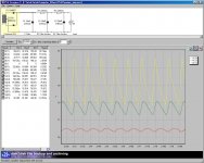
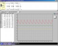
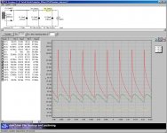
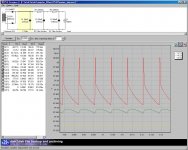
I am attaching four simulation graphs to illustrate. They were simulated using PSU2. Using LTSpice would produce simular result.
The first graph comes from my planned PSU for my new amplifier. I assumed 5A current draw.
In the second graph, I doubled the amount of capacitance. As you can see, the voltage has not changed by much.
The third and fourth graphs are the same except with idle current of 65mA. See doubling the amount of capacitance has not changed much the voltage.
From these 4 graphs we can also see that the doubling the capacitance has not changed much of the voltage sag when large current is drawn.
That was why I suggested that the amount of capacitance has more to do with ripples and THD-N than to amplifier power.
Please correct me if I am wrong.
Attachments
shouldn't you be thankful you got fuses in there? what could have happened other wise?
Tony,
I think I will be extra careful when I test the new amps this time around and not to make mistakes.
AndrewT gave a valid reason. In all of the previous cases in which fuses were burnt, only one fuse in one rail got burnt at a time, not both. The result was that large amount of DC was placed at the output. Perhaps that was because I was poking around with a probe of a scope or multimetre, and perhaps for once I shorted the output terminals. Unless I am convinced that both rail fuses will always get burnt at the same time, I can't see any point having the rail fuses.
Since we can't place too much capacitance after the rail fuse, the increase of power supply impedance would probably cause some measurable hence audible degradation of THD-N figures above 10kHz.
Regards,
Bill
Read the thread - especially the posts by me and gootee. If you have poor PSRR in your amplifier circuit then you will need bigger caps. Even with perfect PSRR you still need caps which are sufficiently large to avoid peak voltage limiting, but diminishing returns set in. Once the cap is big enough, you only get small improvements in power output as the cap gets bigger. Once in this region, it will be better to have a bit more secondary voltage from the transformer (or redesign the output stage so it drops less voltage).HiFiNutNut said:That was why I suggested that the amount of capacitance has more to do with ripples and THD-N than to amplifier power.
Please correct me if I am wrong.
Read the thread - especially the posts by me and gootee. If you have poor PSRR in your amplifier circuit then you will need bigger caps. Even with perfect PSRR you still need caps which are sufficiently large to avoid peak voltage limiting, but diminishing returns set in. Once the cap is big enough, you only get small improvements in power output as the cap gets bigger. Once in this region, it will be better to have a bit more secondary voltage from the transformer (or redesign the output stage so it drops less voltage).
I totally agree with that and have no dispute at all.
What I was trying to say is that the cap "that is big enough" does not need to be very big to reach most of the desired amplifier current and power, after which, any increase of capacitance has only a small impact on the amplifier current and power, but will improve on PSRR. How much capacitance is necessary after that point depends on the PSRR of the amplifier and the target THD-N figure.
Tony,
I think I will be extra careful when I test the new amps this time around and not to make mistakes.
AndrewT gave a valid reason. In all of the previous cases in which fuses were burnt, only one fuse in one rail got burnt at a time, not both. The result was that large amount of DC was placed at the output. Perhaps that was because I was poking around with a probe of a scope or multimetre, and perhaps for once I shorted the output terminals. Unless I am convinced that both rail fuses will always get burnt at the same time, I can't see any point having the rail fuses.
Since we can't place too much capacitance after the rail fuse, the increase of power supply impedance would probably cause some measurable hence audible degradation of THD-N figures above 10kHz
Regards,
Bill
easier said than done.... Murphy makes a strong presence...
in that amp i posted which is a super leach, main filter caps are 68,000ufd/100volt computer grade types, after the fuses are pcb mounted decoupling caps of about 100ufd per rail....
never had any issues with that arrangement, i employed a soft start circuit using relay, and a speaker protector circuit using relay, the speaker output terminals are not fused...any output dc greater than 1 volt(such can happen when one rail fuse blows) and the relay is turned off preventing damage to the speakers......this worked for me real time..this is my experience...don't know about others...
..
HiFiNut,
This thread is about all of that. Neither of us is disagreeing with you but we have already developed equations for your "big enough", "not very big", and "most of", and are intimately familiar with the behaviors you are trying to describe.
Equations relating the PSRR, THD, and C would be a welcome addition, though.
Tom
OK; I thought you were disagreeing with the findings of the thread.HiFiNutNut said:What I was trying to say is that the cap "that is big enough" does not need to be very big to reach most of the desired amplifier current and power, after which, any increase of capacitance has only a small impact on the amplifier current and power, but will improve on PSRR. How much capacitance is necessary after that point depends on the PSRR of the amplifier and the target THD-N figure.
How big the cap needs to be depends mainly on the transformer voltage and the claimed/stated power output. You can design a 100W amp, use a smaller cap and then just call it an 80W amp. On the other hand, if you use a truly massive cap you might be able to describe as a 120W amp.
Hifi started with +-40mF and went up from there. That in my book is good enough for 4ohms speaker driving, where transient currents can approach 30Apk.
15Apk from +-20mF is usually good enough for (very) good LF performance into 8ohms speaker.
I think Hifi's examples would be much more illustrative had he reduced the supply rail capacitance to <+-20mF maybe even used +-10mF and +-4700uF as seen in some builds.
15Apk from +-20mF is usually good enough for (very) good LF performance into 8ohms speaker.
I think Hifi's examples would be much more illustrative had he reduced the supply rail capacitance to <+-20mF maybe even used +-10mF and +-4700uF as seen in some builds.
Hifi started with +-40mF and went up from there. That in my book is good enough for 4ohms speaker driving, where transient currents can approach 30Apk.
15Apk from +-20mF is usually good enough for (very) good LF performance into 8ohms speaker.
I think Hifi's examples would be much more illustrative had he reduced the supply rail capacitance to <+-20mF maybe even used +-10mF and +-4700uF as seen in some builds.
Good analysis. Agreed.
This thread is about all of that. Neither of us is disagreeing with you but we have already developed equations for your "big enough", "not very big", and "most of", and are intimately familiar with the behaviors you are trying to describe.
Thanks for all that. I am yet to use your Spreadsheet as my Excel version is very old at home and at work I cannot download anything from the net.
Equations relating the PSRR, THD, and C would be a welcome addition, though.
That is exactly my point.
- Status
- This old topic is closed. If you want to reopen this topic, contact a moderator using the "Report Post" button.
- Home
- Amplifiers
- Power Supplies
- Power Supply Resevoir Size