I did promise some pictures.
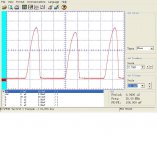
The first is a 24 VCT flatpack transformer driven two diodes into a capacitor (10,000 uf) and 50 ohm resistor. Note the unbalanced peaks which can indicate diode mismatch or unbalanced windings.
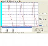
The second is the same circuit with only a 470 uf Capacitor doing the filtering and a toroid transformer with more than 10 times more current capability.
So you can get an idea of the maximum and minimum charging times. Note on the toroid it is the back side that lingers!
The first is a 24 VCT flatpack transformer driven two diodes into a capacitor (10,000 uf) and 50 ohm resistor. Note the unbalanced peaks which can indicate diode mismatch or unbalanced windings.
The second is the same circuit with only a 470 uf Capacitor doing the filtering and a toroid transformer with more than 10 times more current capability.
So you can get an idea of the maximum and minimum charging times. Note on the toroid it is the back side that lingers!
Attachments
I think the question is more complicated than it looks. Depends of PA topology, PS type and so on. I'll give an example.
There was japanese patent from '70s that prevent voltage drop to driver stages. The sound quality improvement is significant.
There is more issues. No one rectifier 'love' big capacitors. The diode recovery can inject significant spikes in the rails. Sometimes the 'shunt 100nF' to the main electrolytes are crucial ... so on.
Other things. If you have 'magnificent' sound in 75% from rated power is beter that 'good' sound in all power range ....
")
There was japanese patent from '70s that prevent voltage drop to driver stages. The sound quality improvement is significant.
There is more issues. No one rectifier 'love' big capacitors. The diode recovery can inject significant spikes in the rails. Sometimes the 'shunt 100nF' to the main electrolytes are crucial ... so on.
Other things. If you have 'magnificent' sound in 75% from rated power is beter that 'good' sound in all power range ....
Attachments
Hello,
Why is the scale voltage only 20mV ??
Regards.
We are measuring current! The scope is calibrated in voltage it is a small resistor of .1 ohms in the ground leg we are viewing.
Here is a question that relates. Ed is measuring some Signal transformers that are closely related to some I'm having problems with.
The design was worked out with a sample flatpack transformer from 5 years ago. All was fine. New transformer arrives, current production. High pitch buzz from transformer. Check primary inductance, measures about 20% less. I think new transformer is running closer to saturation on the same line voltage. If I select a different transformer that allows me to run the primary at 1/2 line voltage the flux is less. What limits the power at this stage? Flux (regulation and heating) or wire resistance and losses? How can I calculate the available VA? Is it 1/2, 1/4 or less than the original rating?
The design was worked out with a sample flatpack transformer from 5 years ago. All was fine. New transformer arrives, current production. High pitch buzz from transformer. Check primary inductance, measures about 20% less. I think new transformer is running closer to saturation on the same line voltage. If I select a different transformer that allows me to run the primary at 1/2 line voltage the flux is less. What limits the power at this stage? Flux (regulation and heating) or wire resistance and losses? How can I calculate the available VA? Is it 1/2, 1/4 or less than the original rating?
If the inductance is 20% less that would suggest there are 10% fewer turns. So NI wolud also be 10% less.
I would run it at 240 VAC 50 Hz into a load and look at temperature rise. Flat packs don't have as buried windings as do over-under.
Signal does rate their VA by core size. So they could be using a higher temperature insulation.
Of course for a full wave bridge with dual rails the derating should be to 45%.
I would expect core losses to be equal to wire losses. Since you can measure coil resistance you can try a loaded unloaded measure and then load it to match that. Then take its temperature.
If you use the 240 input with 120 volts. Then your core losses almost go away and you have the dominant loss as the windings temperature rise. So my feel is 70.7% of rated VA as core heat and wire heat do add but they don't occur at the same.
That test would be to measure temperature rise as rated compared to as you want to use it. Let me know about what VA you are looking at and I may be able to run it.
Last edited:
I am looking at the IF-24-12 and the IF-30-12. I'll restrap one for 240V and see if the noise drops acceptably. I was surprised the see a change like this on a very mature product. The fact that it is fully potted and still buzzes is really annoying, especially when you are a week from production.
I checked the primary DCR. It went from 31 Ohms to 22 Ohms on the new transformer. This is a big change and one I may not be able to work around. Redesing #23 for the stupid power supply. Triad has some cheap ($20) 24 VA toroids. I hope to have one next week and see if that gets the buzz problem behind me. Unfortunately it will have higher primary to secondary capacitance.
Demian
I went through my collection and don't any of those. But I did find a nice 1 watter that I now have hooked up under full load. Tomorrow I'll run it at half voltage and see what load gives the same primary coil heat.
For the others buzz usually means DC on the AC power line. Small cores shift their magnetic operating point faster than do larger cores. When that happens the transformer looses efficiency and can buzz.
What Demian seems to have is a batch of transformers without enough turns on the primary that also causes more of the AC period to be in or near saturation.
Demian we cross posted/
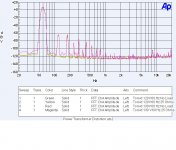
I have that Triad transformer. Attached is the distortion curves for it. They are great!
On the LP-24-1000 which is very close I get 34.9 ohms wired for 120 volts on the primary. No doubt you have bad product!
I have that Triad transformer. Attached is the distortion curves for it. They are great!
On the LP-24-1000 which is very close I get 34.9 ohms wired for 120 volts on the primary. No doubt you have bad product!
Attachments
Last edited:

I have lF-24's that buzz as badly and the old sample works fine. I'll check the 24VA samples for primary DCR. I think Signal had to pull some cost out of the parts. If the Triad is that cheap and works then Signal has further competitive issues. I wish the triad was PC mount but I don't have enough height for it on a board anyway.
- Status
- This old topic is closed. If you want to reopen this topic, contact a moderator using the "Report Post" button.
- Home
- Amplifiers
- Power Supplies
- Power Supply Resevoir Size