Reservoir Capacitance Upper/Lower Bounds Spreadsheet
Attached is a spreadsheet that implements some equations for calculating the upper and lower bounds of the minimum required reservoir capacitance, for a power amplifier.
It only implement the equations that use an approximate value for the caps' ESRs, based on the capacitance and the voltage rating.
The spreadsheet uses equations (5a) and (6a), from the derivation at http://www.diyaudio.com/forums/chip-amps/230787-lm3875-gainclone-too-much-treble-3.html#post3403946 .
Also attached are some screen images, for some chipamp cases that I looked at, with the spreadsheet.
(Excel's plotting is not very good, especially when the scaling is not being automated with Visual Basic. So users of the spreadsheet will probably have to know how to click on the axis labels of a plot, then right click and seldct "Format Axis", and change the minimum and maximum axis limits, if necessary.)
Spreadsheet users, please edit the vertical plot label and change "Capacoitance" to "Capacitance".
Cheers,
Tom
Attachments


Last edited:
Here's another way of doing the math that yields curves going the opposite direction. Easier on the bridge diodes and power factor too.
I briefly describe how to work back through the PSRR of the amp's implementation to determine the acceptable ripple to signal ratio in the linked post. A similar workback based on noise floor is useful as well as there's no particular point in improving regulation or reducing ripple once the amount of supply wiggle appearing on the signal output is below the amplifier's noise floor. I can type up an example if you're interested, though not until tomorrow unfortunately---got work + stuff after work today.I'm not sure how to apply it to determining the minimum required reservoir capacitance.
Thank you. Perhaps I spared you some time browsing Wikipedia? I do need to update my audio page as it's quite old, but keep spending the time writing posts on DIYA instead.(but why did you have to do that, you even forced me to read your bike page)
 My basic motivation is that in audio design requirements aren't usually well determined, with the result that there's no good way of saying "this design should be good enough, let's build it and see if it delivers the expected performance". I've been looking into common mode rejection requirements lately and it's kind of tricky to implement a signal chain whose signal to noise ratio with respect to ground movements is lower than that of even a fairly modest DAC. Supply ripple management alone isn't necessarily good enough but I won't say I've clear understanding as yet of where supplies need to track ground or common mode motion relative to each other and over what bandwidth stable tracking can be achieved.
Correction
The statement in boldface, in the quote above, is INCORRECT.
Equation (17), above, came from:
(13): Δv(t) = ( a / ωC )∙( 1 - cos(ωt) ) + ESR∙a∙sin(ωt)
which is from post 169.
Equation (17) was for a capacitor that was only supplying the current for the first 1/4 cycle of a sine signal.
But, for reservoir caps, as alluded to farther above, we would want to consider the full 1/2 cycle of the sine signal that each power rail handles.
In that case, the maximum Δv(t) is at the end of the sine's half cycle, and sin(180) = 0. So the ESR term drops out!
We end up with:
(17a): (17): C ≥ Δi / ( π∙f∙Δv)
with NO ESR term, which is nice.
<snipped>
Solving for C and setting the proper inequality gives
(17): C ≥ Δi / ( 2πf∙(Δv - (ESR∙Δi)))
Equation (17) gives the capacitance value, C, that would be required in order to supply the current for the first quarter-cycle of a sine signal of frequency f (in Hz), with 0-to-peak amplitude Δi Amperes, while causing the voltage across the capacitor to dip by no more than your choice of Δv Volts.
<snipped>
If we still want to just account for the whole sine wave, we should be able to simply double the C value given by equation (17), since we're considering only the positive or negative half-cycle, but not both, and the other half of the half-cycle of a sine wave is symmetrical and thus encloses the same area (its integral), i.e. the same amp-seconds value, as the first half.
<snipped>
The statement in boldface, in the quote above, is INCORRECT.
Equation (17), above, came from:
(13): Δv(t) = ( a / ωC )∙( 1 - cos(ωt) ) + ESR∙a∙sin(ωt)
which is from post 169.
Equation (17) was for a capacitor that was only supplying the current for the first 1/4 cycle of a sine signal.
But, for reservoir caps, as alluded to farther above, we would want to consider the full 1/2 cycle of the sine signal that each power rail handles.
In that case, the maximum Δv(t) is at the end of the sine's half cycle, and sin(180) = 0. So the ESR term drops out!
We end up with:
(17a): (17): C ≥ Δi / ( π∙f∙Δv)
with NO ESR term, which is nice.
It's reasonable to assume voltage drop due to ESL is negligible at mains frequencies but isn't the above off by a factor of pi/2 for full wave rectification? For leading edges the negligible ESL assumption may or may not hold for home audio given decent layout and surface mount; 1V/us or so into a speaker isn't a particularly noticeable pull from a supply with an ESL of a few nH. If it's closer to a uH then it's probably not so negligible.
ESL is one of my main interests. But that post was actually about the ESR (not ESL) term dropping out of the equation for the minimum capacitance needed to supply a single half cycle of a sinewave audio signal current, for a given peak current and frequency, and a specified drop in the capacitor voltage. The lowest fequency is the worst case, there.
Please read post 169. This is only related to rectification in the sense that the equation might not be applicable as-is below the rectified mains fequency, if used in the context of reservoir capacitance.
Decoupling capacitance at the point of load is a different (and more interesting to me) story, where the inductance can be a key factor in builds that do not include a ground plane, as many here do not.
Last edited:
I did read several of the linked posts; in the case of negligible ESR and ESL the half cycle voltage drop derivation should yield the full wave rectification formula if the current is taken to be the RMS value---in this case, f just happens to be something other than the mains frequency. I can see a sqrt(2) scaling factor depending on how current is defined, but don't see what would generate the pi.
Well, I do sometimes make mistakes. But this isn't one of them!
(I do verify most of this stuff in LT-Spice, at least, before posting.)
O ye of little faith!
ω = 2πf !
Try not to kick yourself too hard.
Seriously, the equation is correct. If you think it should come out differently, then show your work!
Also, I said nothing about anything being "negligible". I mentioned that ESR "dropped out of the equation" (and it was clear that was because I was only evaluating it at the endpoint), not that it was negligible. In fact, it's not negligible. It is usually dominant. And if I need that equation then I would need to re-insert ESR and find the correct equation for the true minimum, since ESR will usually cause it to be less than for an ideal capacitor.
Last edited:
Yes, little faith; steps are skipped and result is off by a scaling factor. It's not that big of an error---3dB---so if one chooses design based on the result anyway there's probably minimal harm done; going from the usual guesswork to a not bad approximation is significantly more design than happens in a lot of DIY. If one's trying to get that last few dB it's Spice, parameter sweeps, and a pile of RLCG parasitic models anyway.
The spreadsheet I posted doesn't use that equation.
But yes, the capacitance values in the last spreadsheet I posted are 2X too high, due to a transcription error (and then me not checking carefully-enough). I am writing a post that includes that information, but which is not about that. I think you might find it interesting.
But yes, the capacitance values in the last spreadsheet I posted are 2X too high, due to a transcription error (and then me not checking carefully-enough). I am writing a post that includes that information, but which is not about that. I think you might find it interesting.
THIS seems interesting!!
ALL,
Someone tell me if I've gone mad (AFTER reading this, please ) This seems too good to be true. It seems like I have found the Holy Grail for reservoir capacitor calculations.
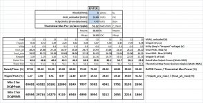
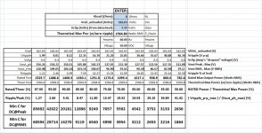
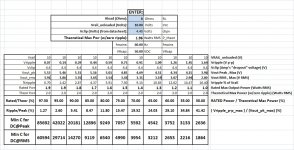
I stumbled upon "an invariance", while playing with the last spreadsheet I posted... (LOOK at the attached thumbnails! Notice the wide variation in the output power ratings (et al), and NO variations in the required capacitances (or certain ratios)!)
(By the way, the C values are 2X what they should be, in that spreadsheet. I will attach a new one, below.)
I happened to set up a series of calculations (of the minimum capacitance to prevent clipping) that were based on the max rated RMS sine output power DIVIDED BY the theoretical maximum RMS sine output power.
For the theoretical maximum output power, I just assumed that the ripple could be zero which meant that I used a peak output voltage of Vrail_unloaded - Vclip, instead of Vrail_unloaded - Vclip - Vripple, to calculate the "theoretical" max output voltage peak level and the RMS power.
Then I set up Excel to calculate the ripple and Vpeak values needed, to set up a row of cases, for which I would have it calculate the minimum capacitances. i.e. I set up columns for fixed-percentage cases of "rated max power divided by theoretical max power", e.g. 97.5%, 95%, 90%, 80%, ..., 50%, so I could see how fast the capacitance went up as the voltage space for the ripple was squeezed toward zero.
So I did all of that. The inputs were the usual things, like load R, Rail voltage, vclip, fmains, and the capacitor's voltage rating (since I was using the "ESR approximation" version of the equations, which, by the way, I got right when re-capping earlier work at http://www.diyaudio.com/forums/chip-amps/152471-finalizing-tda2050-lm3886-2.html#post3363511 but somehow got wrong while finally figuring out how to eliminate all but one variable, at http://www.diyaudio.com/forums/chip-amps/230787-lm3875-gainclone-too-much-treble-3.html#post3403946 ).
Anyway, I noticed that when I changed the rail voltage, none of the calculated capacitance values changed! NOTHING I CHANGED changed the capacitance values, except the load resistance. And that changed them only by the expected scale factor!
For any amplifier from 2 Watts to over 1500 Watts (and more, I'm sure), if you want, for example, the maximum p-p ripple voltage to be 7.59% of the peak output voltage, then the minimum capacitance required to prevent clipping, if your output is the worst-case DC at the peak level, is always the same (> 12896 uF). And for the same thing, except to prevent clipping for a DC output at the rated max RMS level instead of the peak level, then the capacitance required will always be the same, i.e. > 9119 uF (assuming, of course, that my calculations were correct).
(There WILL be a slight change, of course, if the capacitor ESR changes. For the examples, I left it the same, just to make the point. But obviously, for 163V rails you wouldn't use 50V caps. But putting in 200V caps didn't change it all that much. And that's not the point, anyway, but I figured I needed to pre-emptively explain that, for the nitpickers who might also miss the main point. Please don't post about that.)
So that got me really excited.
I finally plotted the row of capacitances versus the row of Vripple/Vpeak values. And THEN I let Excel do a curve fit. Sure enough, it found a perfect fit:
y = 109167 / x
I was using, for x, 100 * Vripple_p-p / Vout_pk (assuming rated max output). And y was the calculated minimum capacitance to prevent clipping (for DC output at Vout_pk, which is my chosen worst case).
That gives:
C_min(pk) = 1091.67 * Vout_pk / Vripple_p-p (my "upper bound" minimum)
for the "DC load at max rated peak" method.
For the "Dc load at max rated RMS" method, I got:
C_min(rms) = 771.92 * Vout_pk / Vripple_p-p (my "lower bound" minimum)
The spreadsheet will follow.
Cheers,
Tom
ALL,
Someone tell me if I've gone mad (AFTER reading this, please
) This seems too good to be true. It seems like I have found the Holy Grail for reservoir capacitor calculations.I stumbled upon "an invariance", while playing with the last spreadsheet I posted... (LOOK at the attached thumbnails! Notice the wide variation in the output power ratings (et al), and NO variations in the required capacitances (or certain ratios)!)
(By the way, the C values are 2X what they should be, in that spreadsheet. I will attach a new one, below.)
I happened to set up a series of calculations (of the minimum capacitance to prevent clipping) that were based on the max rated RMS sine output power DIVIDED BY the theoretical maximum RMS sine output power.
For the theoretical maximum output power, I just assumed that the ripple could be zero which meant that I used a peak output voltage of Vrail_unloaded - Vclip, instead of Vrail_unloaded - Vclip - Vripple, to calculate the "theoretical" max output voltage peak level and the RMS power.
Then I set up Excel to calculate the ripple and Vpeak values needed, to set up a row of cases, for which I would have it calculate the minimum capacitances. i.e. I set up columns for fixed-percentage cases of "rated max power divided by theoretical max power", e.g. 97.5%, 95%, 90%, 80%, ..., 50%, so I could see how fast the capacitance went up as the voltage space for the ripple was squeezed toward zero.
So I did all of that. The inputs were the usual things, like load R, Rail voltage, vclip, fmains, and the capacitor's voltage rating (since I was using the "ESR approximation" version of the equations, which, by the way, I got right when re-capping earlier work at http://www.diyaudio.com/forums/chip-amps/152471-finalizing-tda2050-lm3886-2.html#post3363511 but somehow got wrong while finally figuring out how to eliminate all but one variable, at http://www.diyaudio.com/forums/chip-amps/230787-lm3875-gainclone-too-much-treble-3.html#post3403946 ).
Anyway, I noticed that when I changed the rail voltage, none of the calculated capacitance values changed! NOTHING I CHANGED changed the capacitance values, except the load resistance. And that changed them only by the expected scale factor!
For any amplifier from 2 Watts to over 1500 Watts (and more, I'm sure), if you want, for example, the maximum p-p ripple voltage to be 7.59% of the peak output voltage, then the minimum capacitance required to prevent clipping, if your output is the worst-case DC at the peak level, is always the same (> 12896 uF). And for the same thing, except to prevent clipping for a DC output at the rated max RMS level instead of the peak level, then the capacitance required will always be the same, i.e. > 9119 uF (assuming, of course, that my calculations were correct).
(There WILL be a slight change, of course, if the capacitor ESR changes. For the examples, I left it the same, just to make the point. But obviously, for 163V rails you wouldn't use 50V caps. But putting in 200V caps didn't change it all that much. And that's not the point, anyway, but I figured I needed to pre-emptively explain that, for the nitpickers who might also miss the main point. Please don't post about that.)
So that got me really excited.
I finally plotted the row of capacitances versus the row of Vripple/Vpeak values. And THEN I let Excel do a curve fit. Sure enough, it found a perfect fit:
y = 109167 / x
I was using, for x, 100 * Vripple_p-p / Vout_pk (assuming rated max output). And y was the calculated minimum capacitance to prevent clipping (for DC output at Vout_pk, which is my chosen worst case).
That gives:
C_min(pk) = 1091.67 * Vout_pk / Vripple_p-p (my "upper bound" minimum)
for the "DC load at max rated peak" method.
For the "Dc load at max rated RMS" method, I got:
C_min(rms) = 771.92 * Vout_pk / Vripple_p-p (my "lower bound" minimum)
The spreadsheet will follow.
Cheers,
Tom
Attachments
Last edited:
Spreadsheet for Calculating Reservoir Capacitance, et al
Attached is the spreadsheet mentioned in my previous post.
(P.S. I meant to quote 8.47% instead of 7.59%, in my last post.)
Now I guess I need to derive the expressions for the coefficients that the curve-fitter came up with. <grin>
Cheers,
Tom Gootee
Attached is the spreadsheet mentioned in my previous post.
(P.S. I meant to quote 8.47% instead of 7.59%, in my last post.)
Now I guess I need to derive the expressions for the coefficients that the curve-fitter came up with. <grin>
Cheers,
Tom Gootee
Attachments
Last edited:
What you've found is that C = QV; for ripple to vary with rail voltage it would have to be something other than a linear relation.Someone tell me if I've gone mad (AFTER reading this, please
That's why this link from the previous page makes no mention of the supply level (other than the tacit assumption that one's designing the rails to Vnominal = Vmin + Vripple so that special casing to handle Vripple > Vnominal or the amp shutting down below Vmin isn't needed).If you do a more exensive analysis which accounts for additional factors there is a weak relation between ripple and supply, mainly with regards to the transformer's regulation interacting with the bridge's conduction angle. It's not usually worth worrying about as it's swamped by mains variability and easily mitigated by appropriate trafo choice.
Ah! Makes sense. And if I take i = C dv/dt, i.e. C = i / ( 2 f vripple) plus the second curve-fitted equation above, C = 772 Vout_pk / vripple, so i /2f = 772 Vpk, and Vpk/sqrt(2) = i Rload, I can probably get close to the correct number for Rload.
By the way, what is the rectifier equation to which you referred?
By the way, what is the rectifier equation to which you referred?
Last edited:
Rload ~= Vrail_average / Irms. Ohm's law and small signal approximation as usual.
I wouldn't say there's a rectifier equation per se, but a simple model of the system is an ideal transformer + effective source impedance along with an ideal voltage source for the bridge diode forward drop + equivalent diode resistance. It's only a few elements so turning the analytic crank to apply KCL/KVL is no big deal; series expansion and truncate the small terms. Kind of useful for a "hands on" kind of understanding, though it doesn't tell you anything a sweep in spice wouldn't do better.
I wouldn't say there's a rectifier equation per se, but a simple model of the system is an ideal transformer + effective source impedance along with an ideal voltage source for the bridge diode forward drop + equivalent diode resistance. It's only a few elements so turning the analytic crank to apply KCL/KVL is no big deal; series expansion and truncate the small terms. Kind of useful for a "hands on" kind of understanding, though it doesn't tell you anything a sweep in spice wouldn't do better.
I asked because I did what might be called "a deep dive" into the "simple" transformer/rectifier/capacitor power supply circuit. It's basically impossible to come up with a "nice" closed-form solution, unless as you just mentioned you use a series expansion and truncate it. But I didn't want the approximations. I acquired and read most of the papers, back to the 1940s. Tried to relearn some of the mathematics and electronics that had rusted away, which was actually quite rewarding. I decided to do a numerical solution. I was worried about calculating when the rectifiers turn on and off, since that's normally a transcendental equation with no closed-form solution, i.e. "where does an exponential meet a sinusoid?", and is where many authors used the series expansion to advantage (or the LambertW function). But I learned that one of the great things about solving differential equations numerically is that at every instant, you also have the derivatives available to use in any calculations.
I would have thought you had seen it, if you followed this thread. I did a PDF write-up (minus references), and wrote my first VBA macro for Excel. And it works! It's actually a pretty-useful tool. And most people won't bother with spice (although I did nothing but that, for several years, so I could no longer imagine why).
Please have a look:
PDF is at:
http://www.diyaudio.com/forums/power-supplies/216409-power-supply-resevoir-size-166.html#post3279883
Excel file is at:
http://www.diyaudio.com/forums/power-supplies/216409-power-supply-resevoir-size-167.html#post3287619
Also in that spreadsheet is a nifty scalable power transformer model, which I use to much greater advantage in LT-Spice. The famous Terry Given had taught me about "per-unitization", right here in this thread, not long before I did the spreadsheet. (Well, he's famous to me, at least.)
Regards,
Tom
Last edited:
The schematic is in the linked Excel spreadsheet, on the first tab's sheet. It includes the leakage inductances and resistances of the windings.
An older LT-Spice implementation is at the link below. It is a subcircuit, in this case, so I don't know if you'll be able to tell what settings come from elsewhere, or not.
http://www.diyaudio.com/forums/power-supplies/216409-power-supply-resevoir-size-137.html#post3189423
The basic idea for the non-ideal parts of the transformer model originally came from AN1679-D at onsemi.com, which I think was written by Christophe Basso.
- Status
- This old topic is closed. If you want to reopen this topic, contact a moderator using the "Report Post" button.
- Home
- Amplifiers
- Power Supplies
- Power Supply Resevoir Size