I asked these questions months ago
If I wanted to make a 400 watt into 8 ohm/ 650watt into 4 ohm amp, what would the power supply specs be?
Should each rail have its own transformer and bridge rectifier and which is better
400 100uf caps
40 1,000uf caps
4 10,000uf caps
1 40,000uf cap
should each output transistor have a local cap and a bypass cap of about .1uf ?
Would anyone have an answer now that the spreadsheet is out?
Thanks for any positive answers...
I am trying to make a decision based upon total cost of a project
I'd say 400x100uF cap's, low ESR/leakage are better, order from PRC = just kidding.
Having a separate PS for each channel is obviously better, in other words a mono-block construction. As Doug Self has discussed in his books, the transformer, filter caps, O/P transistors make up a significant % of the over all costs for a traditional amplfier. Piltron makes some nice transformers. As an example look at the PS design app note from National/TI for evaluating the LME498xxx series of drivers. Lots of information avaliable, keep looking or purchase some of the books like Doug Self or Bob Cordell, they have all the answers to your questions.
Having a separate PS for each channel is obviously better, in other words a mono-block construction. As Doug Self has discussed in his books, the transformer, filter caps, O/P transistors make up a significant % of the over all costs for a traditional amplfier. Piltron makes some nice transformers. As an example look at the PS design app note from National/TI for evaluating the LME498xxx series of drivers. Lots of information avaliable, keep looking or purchase some of the books like Doug Self or Bob Cordell, they have all the answers to your questions.
I am trying to make a decision based upon total cost of a project
Calculate how much each cap option would amount to (order number discount).
3300-4700uF are often cost effective sizes.
(I hope you meant 40,000uF per rail)
My question here is what about the first current pulse at start up would not a smaller cap then a small resistance less than a ohm then a big cap banks stress the transformer and bridge a lot less. My preference is a choke but they are large heavy and expensive and hard to get in a high current form .
You do not want this topology for a BIG power amp, because of the R power loss & slew in keeping those BIG caps charged up.what about the first current pulse at start up would not a smaller cap then a small resistance less than a ohm then a big cap banks stress the transformer and bridge a lot less.
If the initial power surge is too much for the switch/fuses/rectifier(bridge), then you need to have a low resistance/high power 30-100ohm/20W in series to charge the BIG caps up slowly, then short out this series resistor (relay/triac) after the initial surge = soft start ckt.
Last edited:
Should each rail have its own transformer and bridge rectifier and which is better
I'd go for separate windings on the same transformer to minimiize mains noise coupling. But then I'd probably go bridged so as to only need one winding.
400 100uf caps
40 1,000uf caps
4 10,000uf caps
1 40,000uf cap
Nearer to the top - 400 caps is a large amount of soldering and might not buy much advantage - myself I'd aim for 330uF or perhaps 470uF caps. Let's say 121 * 330uF. Its important to get the layout right to minimize inductance though - see Terry G's posts on that from a few months back.
should each output transistor have a local cap and a bypass cap of about .1uf ?
If you think about the current loop you'll notice that that's not really called for unless your zobel network is physically close.
3300-4700uF are often cost effective sizes.
thats funny, yesterday I looking some of those
Nichicon PW series type, 105 degr, 35-50V, ø18x35, 0.018ohm ESR, 3000mA
ordinary hole mount (not snap in)
about 2 EUR each
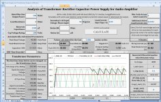
New Power Supply Analysis Tool: Attached
New-and-improved version of spreadsheet is attached, v0.98, in both Excel 2007 xlms and Excel 97-2003 xls file formats. Screen image is also attached.
New features:
- optional non-zero start time for load current ("step input" capability)
- user entry of number of final mains cycles to use for calculation of max, min, avg, and rms psu output voltage, p-p ripple voltage, and peak diode and capacitor currents
I have added quite a bit to the related PDF file, too, and will try to post an updated version later today or tomorrow.
Cheers,
Tom
Attachments
I was talking about low resistance and the time need to charge those large cap is short compared time constant of the bridge . Resistor on the order of less than 1 ohm . see Nelson Pass first watt section for what I was speaking of.You do not want this topology for a BIG power amp, because of the R power loss & slew in keeping those BIG caps charged up.
If the initial power surge is too much for the switch/fuses/rectifier(bridge), then you need to have a low resistance/high power 30-100ohm/20W in series to charge the BIG caps up slowly, then short out this series resistor (relay/triac) after the initial surge = soft start ckt.
Attached is the latest version of the PDF description of the spreadsheet and derivation of equations and numerical solution, etc. (The complete VBA code is available in the spreadsheet downloads.)
Some actual errors were corrected and some significant new material was added. Please delete any older versions, after downloading this version.
Cheers,
Tom
Some actual errors were corrected and some significant new material was added. Please delete any older versions, after downloading this version.
Cheers,
Tom
Attachments
I asked these questions months ago
If I wanted to make a 400 watt into 8 ohm/ 650watt into 4 ohm amp, what would the power supply specs be?
Should each rail have its own transformer and bridge rectifier and which is better
400 100uf caps
40 1,000uf caps
4 10,000uf caps
1 40,000uf cap
should each output transistor have a local cap and a bypass cap of about .1uf ?
Would anyone have an answer now that the spreadsheet is out?
Thanks for any positive answers...
I am trying to make a decision based upon total cost of a project
Krisfr,
The spreadsheet could give you a pretty-good idea of what would work, and how well, and would show any obvious trends or differences for the capacitor configurations. It could also show you what happens when a series resistance is inserted, for example (probably not a good idea- use one that gets switched out after the initial inrush, instead).
But your capacitor configuration questions would be better to investigate with a more-sophisticated type of tool, probably LT-Spice unless you have access to the really-expensive types of PCB-modeling software.
The reason is that with a very large number of parallel capacitors, the physical layout can easily make things like the inductance and resistance of the conductors that connect them become significant and there could be good and bad versions that are very different from each other, even for the same number and value of capacitors.
Your best bet is to take Abraxalito's advice and go back to Terry Given's posts about making a PCB full of caps for each rail. If you use his method, the calculations will be almost simple-enough to do in your head and you can then use a lumped model (a one-capacitor equivalent) with the spreadsheet, or LT-Spice, to explore further.
Regarding using decoupling and bypass caps for each transistor, I would tend to say yes (and either "definitely" or "why not?"), unless they are very close to the edge of a Terry Given capacitor bank.
Cheers,
Tom
Well done for getting that far
Now do some listening tests - how much deviation from this calculated optimum can you go before it matters much?
Are these margins changed much for odd loads likes headphones, frequency specific speakers and weird driver technoilogy like electrostatics?
Compare a single channel with dual mono or multiple psus for single channel.
Will the spreadsheet work for powering the low power bit on an amp? often designs have the input stage and vas having some amount of additional capacitance that looks like a smoothing cap but is in the 200-500uf range.
Agree, the magic trick is the value .......
From i = C x dv/dt (the standard ideal capacitor equation), you can use:
C ≥ (Δi x Δt) / Δv
where you pick or specify the Δv rail disturbance that can be tolerated, when a Δv is caused by a Δi being demanded/allowed to occur (by the pin or device being decoupled by the C), with the Δi starting and finishing within Δt seconds. (Note that longer Δt is the worse case for Δt, but the shortest required Δt can probably also be used, to find a value for a small parallel cap for high-frequency decoupling.)
Alternatively, you can look at Δv / Δi and say it's an impedance; the "target maximum impedance" that the pin or device must see not more than, at all frequencies up to some maximum. Then you can relate it to the capacitance's impedance, 1 / jωC, where ω = 2πf, i.e. angular frequency in radians per second, with f being frequency in cycles per second (Hertz).
Typically, for an audio amp, f would need to go up to somewhere between 80 kHz and 400 kHz. Edge times could also be used to help select f, with f = 1 / (π x trise).
Then, you must also find out what the maximum tolerable inductance is, which will mainly determine the allowable total length of the connections between the decoupling cap and the pins/device being decoupled. For that, you can start with the standard inductor equation, V = L x di/dt and use
L ≤ (Δv x Δt) / Δi
(Or maybe you can figure the L as part of the target maximum impedance. And ESR also gets accounted for.)
Any of the above information might be somewhat wrong, or at least incomplete, because it's been a long time since I worked on the decoupling capacitor calculations, and they weren't quite finished even back then. So please also see the links to some previous posts about it, at http://www.diyaudio.com/forums/solid-state/216409-power-supply-resevoir-size-3.html , or, from very early in this thread. Also recommended are Henry W. Ott's book, "Electromagnetic Compatibility Engineering" and some stuff on the web by Bruce Achambeault (spelling?).
You also usually need a high-frequency BYPASS cap, extremely close to the device pins, because most transistor amplifier toplogies have a hidden positive feedback loop through the power rail, which must be shorted for high frequencies to prevent instability, or marginal stability, which would cause oscillation or ringing at HF.
Last edited:
Forgot to mention that the delta v on the rail is caused by the delta i trying to flow through the inductance of the rails. V = L di/dt so a faster-changing delta i will cause a larger delta v. The purposes of decoupling caps are to minimize the delta v rail disturbance and to deliver the delta i current accurately, when demanded, avoiding the delay time that the rail inductance would otherwise induce, which would result in distortion of the "shape" of the transient current's waveform, in terms of the amplitude vs time. The rail inductance lowers the high-end frequency response and the decoupling capacitance raises it.
Last edited:
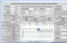
I got the mouse-drag "ZOOM" functionality working, in the spreadsheet's plot, and thought it should be shared. Attached is beta version 0.99.
I am hoping that someone will let me know if it works in any version of Excel other than 2007.
I included an Excel 97-2003 xls file version, and the 2007 xlsm file, both in zipped folders.
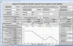
I attached two screen images. In the first one, you can see the rectangle that I just dragged with my mouse, on the plot. The next screen image shows what happened when I released the mouse button.
Notice the three new buttons, just above the plot area. They are "AUTOFIT", "ZOOM", and "UNDO ZOOM".
The AUTOFIT button rescales the plot so that the axes will show every part of the plots. The ZOOM button makes it wait for you to drag a rectangle in the plot area, and then zooms-in so that rectangle fills the plot area, with correctly-scaled axes. The UNDO ZOOM button makes the plot go back to the previous zoomed state. It can handle multiple levels of zoom-undo.
I didn't write the code for those button actions, thankfully. But I did adapt it to use buttons instead of a menu bar (since CommandBars objects are obsolete in Excel 2007.) However, I have noticed that if you click and drag OUTSIDE of the plot area, which the code does NOT prevent, it will cause weird things to happen. So please avoid clicking outside of the plot area, just after pressing the ZOOM button.
Cheers,
Tom
I am hoping that someone will let me know if it works in any version of Excel other than 2007.
I included an Excel 97-2003 xls file version, and the 2007 xlsm file, both in zipped folders.
I attached two screen images. In the first one, you can see the rectangle that I just dragged with my mouse, on the plot. The next screen image shows what happened when I released the mouse button.
Notice the three new buttons, just above the plot area. They are "AUTOFIT", "ZOOM", and "UNDO ZOOM".
The AUTOFIT button rescales the plot so that the axes will show every part of the plots. The ZOOM button makes it wait for you to drag a rectangle in the plot area, and then zooms-in so that rectangle fills the plot area, with correctly-scaled axes. The UNDO ZOOM button makes the plot go back to the previous zoomed state. It can handle multiple levels of zoom-undo.
I didn't write the code for those button actions, thankfully. But I did adapt it to use buttons instead of a menu bar (since CommandBars objects are obsolete in Excel 2007.) However, I have noticed that if you click and drag OUTSIDE of the plot area, which the code does NOT prevent, it will cause weird things to happen. So please avoid clicking outside of the plot area, just after pressing the ZOOM button.
Cheers,
Tom
Attachments
Tom, seems to run fine on 2003, except for the zooming stuff (but maybe operator error).
Thanks very much for the feedback, Klaus!
Would I be correct in assuming the the four scroll-bars do work, for "manual zooming"? All they do is change the plot axes' maximum and minimum values.
- Status
- This old topic is closed. If you want to reopen this topic, contact a moderator using the "Report Post" button.
- Home
- Amplifiers
- Power Supplies
- Power Supply Resevoir Size