You should add the transformer effective secondary resistance to your table, as this is the crucial parameter. VA rating by itself only tells you whether the transformer will get too hot. Two transformers with the same VA could have different resistances.
I think I have figured out how to get the model's component values, during simulation runs: I just create a voltage source that's not connected to anything, and set the voltage to the calculated model-parameter value of interest! Then I can plot the voltage, or better yet, do some useless .MEASURE command on it (like MAX) so that it gets printed in the log file, for each automatic run during a step sweep.
I will get the inductance and resistance (et al) values, for some ranges of base parameters, and report back.
Nice going, Tom ...
Frank
Hi Frank!
Yeah, it started to get a little fun to play with, again.
One cool thing I noticed about the spreadhseet, just by letting it calculate for 50, 75, and 100 Watts, with 28, 30, and 35 Vrms transformer for each of those, was how heavily-dependent everything is on the VRMS of the transfomer output. e.g. 28 VRMS can do 50 Watts RMS easily-enough, with a minimum of 3150 uF. But when you try to go to 75 Watts, it needs a MINIMUM of almost 100000 uF, just to stay out of the "gross distortion" region. I liked seing that pop out, because that type of behavior will make it very clear whenever someone is trying to push a transformer way too close to doing the impossible.
If no one else does it, I will try to generate spreadsheet lines for ALL of the permutations of the Vrms, Rload, and Pmax inputs, within some min-max range and step value for each one, and see what happens!
Then someone could eliminate all of the lines with extremely-large C values, and all of the lines with negative ("impossible" case) C values, and we would be left with a "map" of the areas that are reasonable combinations of Pmax, Vrms, Rload, and C. Should be useful.
I wish I was an Excel and Visual Basic (the macro language for Excel) expert. There are probably some interesting perspectives that could be mined, from the data, especially if a brute force approach wasn't necessary.
Cheers,
Tom
Attachments
Last edited:
This is Terry's territory but something needs to be brought in which considers that transformer behaviour doesn't scale in a linear way, the parasitics for a 500VA unit are not a factor of 5 compared to a 100VA unit. And, that total effective ESR of the caps is very important, if that can be integrated with the spreadsheet ...
Years ago I fooled around quite a bit with VBA, so if you need some input there I can try and lend a hand ...")
Cheers,
Frank
Years ago I fooled around quite a bit with VBA, so if you need some input there I can try and lend a hand ...
Cheers,
Frank
This is Terry's territory but something needs to be brought in which considers that transformer behaviour doesn't scale in a linear way, the parasitics for a 500VA unit are not a factor of 5 compared to a 100VA unit. And, that total effective ESR of the caps is very important, if that can be integrated with the spreadsheet ...
Years ago I fooled around quite a bit with VBA, so if you need some input there I can try and lend a hand ...
Cheers,
Frank
Good points, Frank.
I followed Terry's advice in pursuing the "per-unitized" model scalability, for the transformer model. But I don't really understand the limitations of it. It's undoubtedly "close-enough" within some range of each scalable parameter. But I don't know what that range might be, for each one.
You HAD to mention the capacitor ESR, eh? (grin!) Might as well also try to include the parasitics of the rails, too, I suppose?
Actually, I'm glad you reminded me. I'm not sure I will be able to include it in the spreadsheet. But I will keep it in mind. It would at least change the ripple-amplitude equation, which would then change the equation for the minimum C. But I doubt it will be that simple. A spice simulation circuit, like we've been using, might be the best way, if people need to include more of the parasitics. The equations, which are now what the spreadsheet does, are acknowledged to be "just an approximation". But if the approximation is "close-enough", then it should be "useful-enough" to be used.
Also, we need to keep in mind that in this case, we are worrying about guaranteed avoidance of the gross distortion areas when an amp is running at MAX POWER, and we are simultaneously considering basically every possible phase angle (of a sinusoid) at the same time (by using a square wave). So the results might be for enough of a "worst case" that the finer points don't really even need to be included.
It might be illuminating to see how much capacitance is required when an amp that is otherwise designed to be capable of X Watts RMS will never be used for more than X/2 Watts RMS, for example.
With all of that having been said, please note that the caps' ESRs and the rails' parasitics are currently included in all of my LT-Spice runs (albeit with possibly-suspect calculated ESR values). So the comparisons of the simulations to the equations' (spreadsheet) results are taking all of those into account, at least in some form.
Just for the record, below is what the reservoir caps are using, for parasitics. Also note that I have, so far, been using only one reservoir cap per rail, instead of two or more smaller ones in parallel.
All suggestions would be very welcome.
Capacitance = cap_value
Vrating = 100 V
ESR (Equivalent Series Resistance) = {0.02/(cap_value*Vrating)}
ESL (Equivalent Series Inductance)= 10n
EPR (Equivalent Parallel Resistance) = {1/(0.01*cap_value)}
EPC (Equivalent Parallel Capacitance) = 0
Cheers,
Tom
That spreadsheet is a lot of fun, to play with.
See attached! I don't even NEED a transformer! I could just run straight off of the 120-volt mains and build a 1500-Watt amp, with 33000 uF per rail (or maybe only 11000 uF)!
Or how about 500 Watts with only 1000 uF per rail (or maybe 2200 uF for a "deluxe edition")?!
Might have to worry a little about PSRR... (grin).
Attachments
Last edited:
You should add the transformer effective secondary resistance to your table, as this is the crucial parameter. VA rating by itself only tells you whether the transformer will get too hot. Two transformers with the same VA could have different resistances.
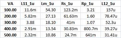
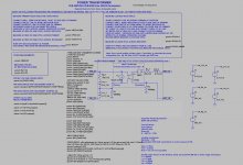
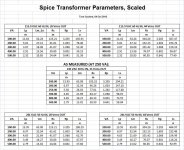
Attached are the transformer parameters (measured off of the LT-Spice plot screen, manually), and the transformer model's schematic.
The measured transformer was a 250 VA secondary of a 500 VA 35-0-35 transformer with a 241-VAC 50 Hz input voltage.
In spice, the transformer was set for the following, when the data in the small table were collected:
; SET TRANSFORMER RATINGS:
.param Vrms_setting=28
.step param VA_setting 100 500 100
.param mains_freq_set=60
.param mains_rms_set=115.9
Attachments
Wow, almost 400 watts per channel stereo amp or one 750 watt subwoofer amp.Well maybe a 1500VA center tapped isolation transformer could make a showing too.
Question:
At what approximate power output level do we say that the average large woofer is highly likely to x-max? Without getting specialist subwoofer products, I'd rather like to know what scale (a ballpark figure in watts) to build a power amp able to drive the average large woofer to capacity? You know, like some decent quality 12" and 15" and the option of a double-woofer 10" for example. So, approximately how many watts (with 10%THD allowed) is needed to drive those examples?
Daniel
I agree with you. I would like to know also what is going to be recommended in the future.
How many transformers for a stereo amp. 1, 2, 4?
How many capacitors per rail to get to the needed farads? 1 big one SOME smaller ones or many little ones.
There are so many questions, and so many answers...
How about 16 or 24 mid-ranges used to make a woofer, each about 4 or 5 inches in diameter? Each in its own box, like an old PE article on the sweet sixteen speakers system.
Why limit the 750 to just sub woofing? You might blow a tweeter or two or three, hehehe.
I would like to see a no holds barred 400 stereo group design build on DIYAudio to be based on the 5U chassis coming in soon. I think that would generate a great deal of interest. But that is MHO. I think a choice of front end topology would make it go a long way too. A OStriper modulo type would work.
You should add the transformer effective secondary resistance to your table, as this is the crucial parameter. VA rating by itself only tells you whether the transformer will get too hot. Two transformers with the same VA could have different resistances.
DF96,
I was finally able to set it up so that the transformer subcircuit parameters' measurements can print automatically, into the LT-Spice log file, making it much easier to acquire them.
I have attached some tables that show the primary and secondary inductances and resistances, and the magnetizing inductance, for the originally-measured input and output conditions, plus two different input and output voltages and line frequencies.
If someone who knows about scaling transformer model parameters would care to comment on how far they might reasonably be able to be scaled, that would probably be quite useful.
Cheers,
Tom
Edit: Added the 250VA case to the "as-measured" table.
Attachments
Last edited:
Nico,
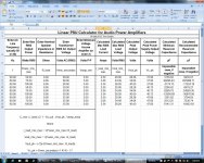
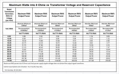
After filling in the spreadsheet I posted earlier, with lots of combinations of transformer voltage and maximum output power, and 8 Ohms for the load, I pulled out some data for a few values of reservoir capacitance and made it all into a table, just to illustrate the trends and to have as a handy reference.
Of course, some assumptions are embodied in the data, such as the 1.7-Volt rectifier drop, and the 3-Volt minimum between the ripple voltage and the output signal voltage. So your mileage may vary. Still, it's an interesting type of table.
Cheers,
Tom
Attachments
Last edited:
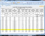
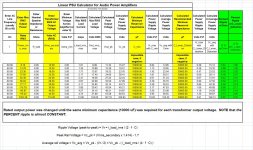
Here are two examples of the latest version of my CMIN-calculating spreadsheet. They each contain lots of combinations of values of the transformer output voltage and the maximum output power. One is for 8 Ohms and the other is for 4 Ohms (They are the same spreadsheet, except for the values entered.). Both .XLS files are in the zip file.
Cheers,
Tom
Cheers,
Tom
Attachments
Interesting. Seems to show that even for high power there is little point in going much above 10000uF, and for lower power diminishing returns set in from 5000uF.gootee said:After filling in the spreadsheet I posted earlier, with lots of combinations of transformer voltage and maximum output power, and 8 Ohms for the load, I pulled out some data for a few values of reservoir capacitance and made it all into a table, just to illustrate the trends and to have as a handy reference.
Turning it around, if you design a 100W amp then find that it can't quite do continuous 100W low bass then you can do one of the folowing:
1. massively increase the capacitance size
2. somewhat increase the transformer size/voltage
3. just call it an 80W amp, with excellent transient capability!
Interesting. Seems to show that even for high power there is little point in going much above 10000uF, and for lower power diminishing returns set in from 5000uF.
Turning it around, if you design a 100W amp then find that it can't quite do continuous 100W low bass then you can do one of the folowing:
1. massively increase the capacitance size
2. somewhat increase the transformer size/voltage
3. just call it an 80W amp, with excellent transient capability!
I did an experiment. First an 70w amp with a 96va (2a) transformer and 10,000u. The low bass just wasn't very good. But I had two of these transformers and they're dual secondaries models. So, I paralleled the secondaries of both, to create a 192va (4a) transformer. The bass was much better. Lastly, I added a second amp for stereo, but the bass did not change. Well, that is somewhat mysterious.
I did an experiment. First an 70w amp with a 96va (2a) transformer and 10,000u. The low bass just wasn't very good. But I had two of these transformers and they're dual secondaries models. So, I paralleled the secondaries of both, to create a 192va (4a) transformer. The bass was much better. Lastly, I added a second amp for stereo, but the bass did not change. Well, that is somewhat mysterious.
Connect one of them to a dummy load
- Status
- This old topic is closed. If you want to reopen this topic, contact a moderator using the "Report Post" button.
- Home
- Amplifiers
- Power Supplies
- Power Supply Resevoir Size