Thanks Krisfr, hopefully Gootee will provide the formulas")
It is easy, don't think I am that smart
See the interesting file that Tom attached to post 1219.I can do a Android app, just give me the inputs and what outputs you want based on formulas. The oscope and DA are out of my scope, and they can be done, but not by me...
I looked at the spread sheet, but I could not directly see the formulas.
My display made some of the fields tiny.
When Tom "Plainly" states what they are I will put it on an app.
I follow most of what has been detailed in this thread, but I wish someone would state the max max of 110 at 60 htz with 15 or 20 amps or 220 at 50. There should be some magic power output and rail voltage combo to be derived a great sounding amp.
Maybe I just want to build the biggest one I can based on 110, then it will loaf along never being stressed, never hitting the rails, over kill my way into the sweet spot.
Is your mains voltage really that droopy? We both live in the USA, but my outlets do 120v@60hz.Maybe I just want to build the biggest one I can based on 110, then it will loaf along never being stressed, never hitting the rails, over kill my way into the sweet spot.
P.S.
Well, the 60hz is wishful thinking--there's a lot of bonus noise content, but the higher pitched signals don't have as much strength as the 60hz; yet the bonus noise content is enough to drive an ordinary transformer, rectifier, caps, setup to a few volts higher unloaded and that makes more rail bounce.
Last edited:
I thought I had already done that! At least for Vrms, which is by far the strongest influence on Cres. I seem to keep repeating myself in this thread. Am I just wasting my time? I thought you had produced a formula too?
In the early days of radio people didn't know how antennas actually worked, so they just played around with different lengths and shapes and established rules of thumb. Then one day someone had a good theory and said "Just put a quarter-wave length of wire straight up into the sky". At first they carried on bumbling around, believing that it couldn't be that simple. Eventually they realised that he was right.
Years later a new generation came along who for reasons we don't understand did not trust theory (or didn't understand algebra - we are not sure which it is). They started trying different antennas. An old-school engineer kept saying "Quarter-wave!", but they ignored him. Curiously, at the same time some of them began asking if anyone had a formula for the right length. How long before they 'rediscover' the right formula? (This story is not entirely historically accurate - it is told to make a point).
As I keep saying, to get the minimum cap value you need to do a ripple calculation (this involves Vrms, Vpk, Rload, Vdrop). You will find that the Cres depends critically on (1.414xVrms -Vpk - Vdrop=Vripple-max). Then double it. This will be close enough. There is little advantage in going bigger, and there may be disadvantages in going much bigger.
DF96,
I understand your point but I think that most people here know how to calculate the reservoir capacitance using the standard approximate formulas, based on an RMS or DC load current. (For example, see Unregulated Power Supply Design, or, for another method, my post #1061 at http://www.diyaudio.com/forums/power-supplies/216409-power-supply-resevoir-size-107.html#post3160168 , but with the + sign changed to a minus sign in step 5. (However, note that in the example at the end, the resulting capacitance was too LOW, by a factor of just over 2. The actual answer should have been 6650 uF instead of 3000 uF. But also note that the calculated value was not "doubled" arbitrarily. The method calculates the C of both rail capacitances as one capacitance, but since they are in series as far as the calculation is concerned, the value has to be doubled to get the two individual rail capacitances.)
I think that I was originally wondering about the possibility of those types of standard methods not accounting for non-constant load currents and the worst-case timing of load-current peaks and charging pulses, while I was investigating just the very first step of finding a general rule for "What C value could and should we use?", with that first step being to see if I could find a way to know the "true" lower bound of the C value, for sinusoidal load currents at the rated maximum output power. I have had limited time and that first step has seemed quite belabored.
Anyway, I think that the part where you say "Then double it." would need to be justified. I'm sorry if you already did that. I know there were a couple of posts of yours, with equations, that I didn't get to study and that I meant to go back to, but haven't yet.
At any rate, my original plan was to try to use simulations to find the ACTUAL lower bound for the C value, for different cases, and then compare that to what the standard equations give, and then try to move forward from there. I think that I am just now finally able to compare the simulation results to the standard equations' results, which I attempt to do, below or in another post.
I do realize that you pointed out, correctly, that it will also depend on the amplifier topology, since the actual absolute-minimum C depends on the minimum voltage that can exist across the amplifier, i.e. between the rail and the high side of the load, with the minimum C being the one that allows the rail voltage to have a worst-case drop that doesn't quite reach Vload_max_peak + Vamp_minimum, for the worst-case timing of a load current peak and the first quarter of a charging pulse. But I can either leave the minimum Vamp as a variable, or, just add a few volts (for a minimum Vce plus a small series resistor), for now, and be close enough for this purpose.
(Yes, it appears that a rail-voltage incursion into the output voltage only occurs during the upward-curving portion of the beginning of a current pulse from the transformer, between zero and the first inflection point. Made me wonder if the second derivative of the transformer current was important.)
On to the standard equations: (I HOPE that someone will check my algebra and my arithmetic!)
From Unregulated Power Supply Design :
Ripple Voltage (peak-to-peak) = Vr = i_load_rms / (2 ∙ f ∙ C)
Peak Rail Voltage = Vc_pk = (Vrms_secondary x 1.414) - 1.4
Average rail voltage = Vc_avg = Vc_pk - (Vr / 2) = Vc_pk - ( i_load_rms / (4 ∙ f ∙ C) )
For the absolute minimum C, we would need:
Vc_avg - (Vr / 2) ≥ Vout_pk + Vamp_min
in order to not have any rail voltage dips gouging into the output voltage.
But Vc_avg - (Vr / 2) = Vc_pk - Vr = Vc_pk - ( i_load_rms / (2 ∙ f ∙ C)) .
So we can re-express what we need as:
Vc_pk - ( i_load / (2 ∙ f ∙ C)) ≥ Vout_pk + Vamp_min
Solving for C, we need to have:
C ≥ i_load / (2 ∙ f ∙ (Vc_pk - Vout_pk - Vamp_min))
That's actually a little better than the "standard" formula, since it also accounts for the minimum voltage across the amplifier. This should give slightly higher capacitance values than the usual standard formulas.
We already know:
i_load_rms_max = √(Power_rms_max / R_load)
Vout_rms_max = √(Power_rms_max ∙ R_load)
Vout_pk = (√2)(√(Power_rms_max ∙ R_load))
Vc_pk = (Vrms_secondary x 1.414) - 1.4
Vamp_min = 3 (Min Vce plus worst-case voltage across the 0.22-Ohm R)
--------------------------------------------
To compare to the four cases for which I recently posted simulation results,
Power_rms_max would be one of 25, 50, 75, and 100 Watts RMS,
giving i_load max rms values of 1.77, 2.5, 3.06, and 3.535 Amps RMS,
and Vout_pk values of 20.00, 28.28, 34.04, and 40.00 Volts peak.
With the 44-0-44 transformer output, we get
Vc_pk = 60.83 Volts peak.
Plugging in those values and turning the crank yields C_minimums of
C = 390 uF, 705 uF, 1100 uF, and 1650 uF, for
Power = 25 W, 50 W, 75 W, and 100 W.
But, with a 240 VA secondary for each rail (a 480 VA transformer), simulations found the "actual" C_minimums to be:
C = 330 uF, 770 uF, 1540 uF, and 6650 uF
------------------------------------------
It appears that the standard equations are assuming an ideal transformer, and that they also don't account for the occasional badly-timed load current peak relative to a charging pulse.
So the standard equations do well when the transformer is ridiculously over-sized compared to the output power spec.
HOWEVER, as I've been saying repeatedly, everything in my simulations depends on how good the transformer models are. And Terry Given just mentioned that it looks a little wacky.
Does anyone have some "typical" values for such a model? (The transformer ratings don't have to be the same as my original ones.)
Hey Terry, I have an LCR meter that I did not have, back when I was doing the original transformer measurements. Could that help to check them? I think that I still have the original 120 VA 25 Vrms transformer that was measured.
Cheers,
Tom
Last edited:
I am sad to have to admit I have given up reading this Thread, mainly because the posts are so long and it was just taking me too long to read and follow all the technicalities.
So I just pop in now and again to see the latest.
The above has me confused.
I use a 35+35Vac transformer for a 100W into 8r0 amplifier.
Why the reference to 44-0-44 Volts transformer?
Is that a peak of the AC waveform? or the AC voltage after applying the transformer regulation, or taken literally as a 44Vac-0-44Vac transformer giving supply rails when powering a quiescent output stage of very approximately +-60Vdc.
I am lost and this may be due to not following the Thread in detail.
Andrew,
I temporarily used a 44-0-44 transformer model in order to try to remove the effects of having a rail voltage that was already relatively close to the maximum peak output voltage (with a possibly-too-weak transformer).
I just wanted to see how the numbers came out, for the highest C that would still make Vrail droop until it corrupted the output.
And I also wanted to see if any trends came into focus better, when there was not so much of a problem with the headroom.
But I'm starting to suspect that the particular transformer model parameters I am using might not be giving very good load regulation.
However, regarding the load regulation, we should also keep in mind that I am simulating with square waves that have the same peak amplitude as would a sine wave that was producing the maximum rated output power. i.e. The square waves produce 2X the maximum rated output power. (But still, the transformer seems like it should handle it way better than it is.)
Regards,
Tom
<snipped>
I'll go and re-measure a 35+35Vac transformer. Volts and ohms only, I have not worked out yet how to do the complicated stuff.
Andrew,
If you have a VARIAC, and a low-value power resistor, that's all you need besides a multimeter.
The complete (and very simple) instructions are printed right in the diagram, at http://www.diyaudio.com/forums/power-supplies/216409-power-supply-resevoir-size-123.html#post3167972 .
You might want to read it to see if my safety warning was adequate, for people playing around with exposed mains connections and no safety devices whatsoever, except their breaker box.
Regards,
Tom
I think you have demonstrated that the 'standard methods' are completely adequate, when used properly i.e. circuit theory actually works OK.gootee said:I think that I was originally wondering about the possibility of those types of standard methods not accounting for non-constant load currents and the worst-case timing of load-current peaks and charging pulses, while I was investigating just the very first step of finding a general rule for "What C value could and should we use?", with that first step being to see if I could find a way to know the "true" lower bound of the C value, for sinusoidal load currents at the rated maximum output power.
The justification is simple: normal engineering caution, combined with broad electrolytic value tolerances (can be 20%). The calculation gives the minimum. There seems to be no harm in increasing this (within reason) so increase it. There is no point, and possibly some harm, in increasing it too much. Hence double it. x3 or x4 would be just as good, although maybe unnecessary.gootee said:Anyway, I think that the part where you say "Then double it." would need to be justified.
The calculations you have done show good agreement with simulations for lower powers. The discrepancy for higher power mainly comes from Vmin being a bit too small. This has little effect at low power (i.e. high ripple voltage) but is critical at high power (low ripple voltage). As you have included the 0.22ohm drop in Vmin (not a good idea, in my opinion) your Vmin should be bigger for greater power. Try repeating your calcs for Vmin=4V instead of 3V.
Including transformer resistance in the calculations gets messy, unless the resistance is sufficiently low that the cap can recharge more or less fully on each mains half-cycle. As I said in an earlier post, this gets worse for really big caps which may be a reason to avoid really big caps.
So we are in a position where we can calculate, with some confidence, the minimum cap value. We can also estimate, roughly, the maximum. Isn't that 'job done'?
Thanks Gootee for the formulas
I will put these into equations for the Android app.
It kinda reminds me of my FORTRAN instructor chiding me for putting the formula for radar slant range distance from target, taking in the consideration, the curvature of the earth in one statement. I keypunched it into 4 punch cards with a single FORTRAN statement. It had 27 closing parenthesizes.
Although these pages of meaningful thought and consensus, seem worth while to making a decision about how much capacitance to put on a amp rail. I can not hardly wait until I can punch in my own criteria and get an answer to my own question. I may be able to make a PC or non smart phone app too.
Thanks for what this all boils down to.
won't be today and probably not tomorrow either.I'll try to fit in the whole test today.
Going back into hospital to sit with my Dad.
Andrew,
good man. I'm doing the same with my wife.
Terry and Andrew,
Our hearts are with you and your loved ones.
Please try to remember to also take care of yourselves. It's easy to forget to do that and you can't do them much good if you get too burned out.
Tom
"I found if i decoupled the front end from the output stage with a resistor and capacitor I could get away with more ripple. "
Try sneaking a diode in there, Hafler did than in many of their designs.
McIntosh used to use CRCRCR sections (like it was in a tube amp) to feed the front end.
Try sneaking a diode in there, Hafler did than in many of their designs.
McIntosh used to use CRCRCR sections (like it was in a tube amp) to feed the front end.
Last edited:
I think you have demonstrated that the 'standard methods' are completely adequate, when used properly i.e. circuit theory actually works OK.
The justification is simple: normal engineering caution, combined with broad electrolytic value tolerances (can be 20%). The calculation gives the minimum. There seems to be no harm in increasing this (within reason) so increase it. There is no point, and possibly some harm, in increasing it too much. Hence double it. x3 or x4 would be just as good, although maybe unnecessary.
The calculations you have done show good agreement with simulations for lower powers. The discrepancy for higher power mainly comes from Vmin being a bit too small. This has little effect at low power (i.e. high ripple voltage) but is critical at high power (low ripple voltage). As you have included the 0.22ohm drop in Vmin (not a good idea, in my opinion) your Vmin should be bigger for greater power. Try repeating your calcs for Vmin=4V instead of 3V.
Including transformer resistance in the calculations gets messy, unless the resistance is sufficiently low that the cap can recharge more or less fully on each mains half-cycle. As I said in an earlier post, this gets worse for really big caps which may be a reason to avoid really big caps.
So we are in a position where we can calculate, with some confidence, the minimum cap value. We can also estimate, roughly, the maximum. Isn't that 'job done'?
Sorry. I cannot agree.
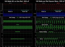
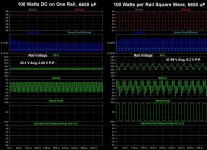
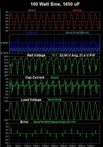
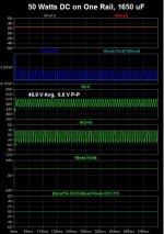
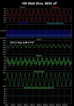
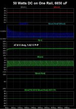
Attached are some plots for comparisons but I will not be able to analyze them until tomorrow or the next day. They include DC, sine, and square wave loads, with 1650 uF and 6650 uF.
Attachments
- Status
- This old topic is closed. If you want to reopen this topic, contact a moderator using the "Report Post" button.
- Home
- Amplifiers
- Power Supplies
- Power Supply Resevoir Size