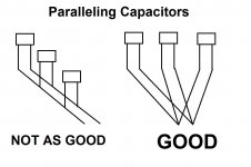
With careful wire/track positioning it might be possible to reduce the effective inductance of capacitors. Two caps in parallel have an average current path which runs between them, so if the wire runs here then the net inductance is minimised.
DF,
Note that I wasn't talking about paralleling caps onto a buss with only two conductors that all of the caps share. Each capacitor would have to have its own two conductors and all of the pairs of conductors would not be connected anywhere except at the decoupling point.
There is no "might" here, that I am aware of. Henry W. Ott describes this technique rather thoroughly, in the latest edition of his book, "Electromagnetic Compatibility Engineering". Also, see some of the material by Bruce Archambeault (sp?), on the web.
Tom
I think that I am following the discussion of wiring the parallel capacitors here but could someone put up a line drawing of the wiring, not in schematic form, but a physical layout. It would be much appreciated. And would the last capacitor be a film cap?
Steven
Argh!! Where does this idea of always throwing in a parallel film cap keep coming from?
Please read the thread about paralleling electrolytics and film caps.
It is NOT, repeat NOT, a good idea, especially way out at the PSU reservoir caps. It MIGHT, but only might, be safe-enough, and would even have a chance of being effective, right at the load, for decoupling.
Similar "discouraging" comments are waiting for the next mention of placing a film cap (or any cap, by itself) across a rectifier diode. <grin>
OK, with that all having been said, the paralleling of multiple capacitors could apply to electrolytics, but could also be applied with any type of capacitors. It is particularly important for decoupling in high-speed applications, when using ceramic or film caps. It can also be necessary for decoupling in audio power amplifiers, where inductance can be too high with only one cap.
I will do a drawing for you, in a few minutes.
Tom
Thank you Gootee, I did propose p (http://www.diyaudio.com/forums/power-supplies/216409-power-supply-resevoir-size-114.html#post3164323)
I am following your hunt for ¬p
I am following your hunt for ¬p
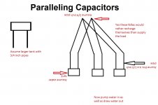
Thank you Gootee. So rather than daisy chain the capacitors we tie all the leads together as if it was a star ground connection. Do all the leads need to be the same length or does that not matter and should the wires all be parallel to each other before the connection?
assume p
No, sorry. When current is needed, the voltage across the common terminals will be lower than any of the individual cap voltages. They will all then supply current when needed, just with superior inductance and resistance parasitics compared to one cap.
Thank you Gootee. So rather than daisy chain the capacitors we tie all the leads together as if it was a star ground connection. Do all the leads need to be the same length or does that not matter and should the wires all be parallel to each other before the connection?
Lengths could be somewhat different. That just changes the parasitics a little, and changes the caps' utilizations (providing current) slightly, unless the differences were large.
Usually, the connections should be as short as possible, since we're usually also worried about the parasitic inductance and resistance of the conductors.
By "parallel to each other", you would mean "not connected together until they reach the point where they join, at the last possible moment, as close as possible to where the capacitance is needed". Geometrically parallel or not would not usually be very relevant, unless maybe we were worried about tiny coupling effects. Electrically parallel is usually all that really matters, as far as "parallel" is concerned.
Thanks Gootee, will tickle your bone tomorrowgot a football game to watch
Enjoy! (That reminds me... there's still some beer in my refrigerator.)
But how do you have time to watch football?
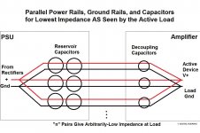
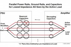
"Parallel decoupling capacitances", taken to one of its logical conclusions:
(Of course, this would be done for each power rail. Only one is depicted.)
Great Tom, thank you!
(taken to extreme the idea, I would go for one only reservoir capacitor, i.e. no Cres-L-Cres. Wouldn't you?)
Stefano
Last edited:
Great Tom,
but taken to extreme the idea, I would go for one only reservoir capacitor, i.e. no Cres-L-Cres.
Wouldn't you?
Stefano
Stefano,
Could you please explain further?
I can't quite picture what you mean. I think that what I showed would give the lowest impedance, as seen by the load, since the Cs would tend to multiply by N and the L and R of the capacitors AND of the CONDUCTORS would tend to be divided by N, where N is the number of duplicated power/gnd rail pairs.
Or did you mean to use only one reservoir cap per pair? Maybe one before they divide and one per pair would be better. Or add one before they divide, just after the rectifiers, so the charging pulse currents could be kept out of the rest of the circuit.
Tom
Stefano,
Could you please explain further?
Or did you mean to use only one reservoir cap per pair? Maybe one before they divide and one per pair would be better. Or add one before they divide, just after the rectifiers, so the charging pulse currents could be kept out of the rest of the circuit.
Tom
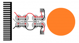
I was just simply imaging the first option. To remove the inductance between reservoir caps. The resonance between the single reservoir cap and the local cap would be damped by the resistive components of the wire in between (so a sort of Cres-Lwire-Rwire-Clocal).
Should I need more capacitance, voilà just add another whole line.
But it's late in the night here, and I've got some red wine.... hic!
Attachments
Last edited:
I was just simply imaging the first option. To remove the inductance between reservoir caps. The resonance between the single reservoir cap and the local cap would be damped by the resistive components of the wire in between (so a sort of Cres-Lwire-Rwire-Clocal).
Should I need more capacitance, voilà just add another whole line.
But it's late in the night here, and I've got some red wine.... hic!
Now I think I understand. But those are assumed to be electrolytic caps and their ESR should be enough damping that we don't have to worry about any resonant LC "tank" circuits being formed. (That WOULD be a danger, if we put a film cap near the electrolytics.)
Your point about just adding another whole parallel pair, if more capacitance is needed, is well taken.
(Yeah, I think I have a nice Cabernet or Merlot here, somewhere. Sounds like a good idea.)
Last edited:
Tom, those graphs reveal a lot of information provided that the observer realises that the output signal (driving the load is fixed) and only the error benefits can be had. Now at what point does the error represent noting more worth pursuing.
From the data you present I would select 6000uF as being overly suitable for all three applications.and will split them into 6 x 1000 uF or even 12 x 500uF, if real-estate is not at premium I would go for 60 x 100uF.
Nico,
Yes, the question is, "How low is low-enough, for the distortion?".
Maybe I will play some music through the simulated amplifier and listen to the result, for different capacitances, and listen for any difference.
I can make the WAV files from the output, for several different capacitance values, and then burn a CD and take it to my good audio system (i.e. not use the computer's sound card to play them).
If the results are interesting, I could even post the WAV files on line.
(I hope I still have that WaveEdit demo software. I definitely can't wait for it to process an entire song.)
Tom
...hope that will also "tastes" like a good idea
Thank you, I simply didn't take in enough consideration the ESR of reservoir caps... (I wrote it was late, etc etc)
Hey, at least you're thinking about the possible resonances! That doesn't even occur to most people. Good work.
- Status
- This old topic is closed. If you want to reopen this topic, contact a moderator using the "Report Post" button.
- Home
- Amplifiers
- Power Supplies
- Power Supply Resevoir Size