Fun stuff about parallel caps
How does each parallel cap see 8 Ohms when there is only a 4-Ohm load?? Impossible. If they are paralleled across 4 Ohms then they each see 4 Ohms.
But it SHOULD be about what the 4 Ohms sees. If the caps are the same as the original, it sees about twice the capacitance, about half as much inductance (ESL), and about half as much ESR. EVERYTHING is improved.
If the two parallel caps are each half the value of the original, then the capacitance stays about the same as the original but the ESL and ESR are probably less than half as much as with one cap, because the caps are smaller and can be placed closer and their connections and lead spacings could be shorter. HF behavior is improved.
Of course, for decoupling, the caps wouldn't usually be right across the load. They'd be from a power rail to the load ground, typically.
But if it was a trick question, then "out with it"!
Last edited:
How does each parallel cap see 8 Ohms when there is only a 4-Ohm load?? Impossible. If they are paralleled across 4 Ohms then they each see 4 Ohms.
But it SHOULD be about what the 4 Ohms sees. If the caps are the same as the original, it sees about twice the capacitance, about half as much inductance (ESL), and about half as much ESR. EVERYTHING is improved.
If the two parallel caps are each half the value of the original, then the capacitance stays about the same as the original but the ESL and ESR are probably less than half as much as with one cap, because the caps are smaller and can be placed closer and their connections and lead spacings could be shorter. HF behavior is improved.
Of course, for decoupling, the caps wouldn't usually be right across the load. They'd be from a power rail to the load ground, typically.
Hehe, I knew that would tickle you. Using I = V/R. Assuming the load is 4 ohms and the voltage is 4 volts. A single cap would release 1A. Now if there are two caps, each cap would release 0.5A . R = V/I = 8 Ohms
All the best. Enjoy the space ship building ")
Harrison,
Curious mind want to know.
And that reminds me I have to complete a paper on advanced composites for a seminar speech I signed on to give.
Steven
gootee,
Is there some theoretical point where adding more capacitors becomes a problem? Do the multiple leads between capacitors end up adding some inductive or resistive problems at some point, or could you theoretically parallel hundreds of small value caps?
Steven
OnAudio,
Just trying to teach engineers how to build better aerospace and automotive parts faster and cheaper. Spaceships would be more fun. but my dylithium crystal are on back order.
Last edited:
but my dylithium crystal are on back order.
Will send you my shipping address, needed some of that

gootee,
Is there some theoretical point where adding more capacitors becomes a problem? Do the multiple leads between capacitors end up adding some inductive or resistive problems at some point, or could you theoretically parallel hundreds of small value caps?
Walt Jung in his 1980 Audio magazine article "Build an Energy Storage Bank" mentioned this, he said at some point adding more capacitance, the lead inductance becomes significant to affect the results....i do hope he chimes in in this discussions...
Sure fire recipe for very dull audio. With massive paralleling, there seems to be some treble killing gyrations going on. That's worse than a choke. It is about as bad as my SD669 capmulti. Oh fail! But I learned that any possible audio processor effects can be installed at the power circuit because whatever you do to the power circuit also affects the output. If on purpose, there's a powerful tool, but powerfully vexing if done by accident.Do the multiple leads between capacitors end up adding some inductive or resistive problems at some point, or could you theoretically parallel hundreds of small value caps?
P.S.
A more customary spot to find the tone control feature is at the amp board's power cap sizes--bigger for more laid back (possibly duller) -or- smaller for more forward (possibly clearer). It isn't entirely a case of no free lunch. An even balance plus extra good noise filtering can get you a combination of both laid back and clearer but at the cost of more time investment.
P.P.S.
Your massively paralleled example is not problematic if the predrive is run on regulators. Well, that's the orthodox fix. I have a cheaper method, at post 1115.
Hi Nico, some updates on the 1DIFFQC . Thanks WSJ, Gootee et al for reviewing PCBs.
http://www.diyaudio.com/forums/solid-state/219354-1diffqc-amplifier-2.html#post3166048
. Thanks WSJ, Gootee et al for reviewing PCBs.http://www.diyaudio.com/forums/solid-state/219354-1diffqc-amplifier-2.html#post3166048
gootee,
Is there some theoretical point where adding more capacitors becomes a problem? Do the multiple leads between capacitors end up adding some inductive or resistive problems at some point, or could you theoretically parallel hundreds of small value caps?
Steven
OnAudio,
Just trying to teach engineers how to build better aerospace and automotive parts faster and cheaper. Spaceships would be more fun. but my dylithium crystal are on back order.
Kindhornman,
IF you could keep all of the leads and connecting conductors completely separated (i.e. also in parallel), ALL the way to the point of load (or wherever you need the capacitance), then adding more in parallel would always continue to be an improvement.
In that case, the inductances of the caps and the leads and confuctors would reduce in exactly the same way that the resistance of parallel resistors reduces. The ESRs of the caps and leads and conductors would also reduce, similarly. And the total capacitance of the capacitors would be the sum of all of the paralleled caps' capacitances. All of those numbers are heading in the right directions as we add more caps/leads/conductors in (true) parallel.
The "theoretical limit" is actually just running out of space. The caps might get difficult to fit, but keeping all of the conductors separate all the way to the point where the capacitance is needed would become impractical at some point. Usually, people switch to using ground and power planes, before they get close to that point.
Even with planes, the problem that can partially ruin the improvement from paralleling is when the conductors are no longer completely separate, i.e. the currents have to share some length of conductor. Then there would be MUTUAL inductance. And that wrecks the algebra somewhat so that the inductances don't fully reduce from paralleling.
One other thing to realize is that IF the leads and conductors CAN also be kept in parallel and separated, then you can use much longer connections and still get a large benefit.
e.g. two conductor pairs in parallel have half the inductance of one that's the same length. But they have the SAME inductance as one that's half their length.
So if you had to put two capacitors twice as far away as one original one, maybe because they wouldn't fit otherwise, the lead inductances would total to the same inductance as one capacitor only half as far away, but the capacitors' total inductance would still be halved, while the total capacitance would now be double that of just one cap.
Extending that, you could use n caps, n times farther away than one, and still divide their total inductance by n, and have n times the capacitance, while NOT increasing the total conductor self-inductance!
And it's likely that the connections wouldn't have to be n times as long, for n capacitors. So the total connection self-inductance can often also be reduced.
Cheers,
Tom
Last edited:
Tom, I take it that you promote the idea of the caps be used as in a star ground, or am I miss understanding it. In such a case one would be saddled with several LRC circuits.
Two distinct possibilities exist in that one is of several hi Q resonators and different frequencies which may easily excite with switching transients and the other that of causing differential currents to flow from different capacitors if the LCR circuits being grossly unmatched.
The first remark may have a positive effect of several narrow filters in parallel actually increases to overall bandwidth and reduces the Q thus suppresses switching transients.
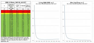
Attached are some data and plots for three sizes of power supplies, with an amplifier load driving max-power square waves into an 8-Ohm load.
The square waves use double the rated power of the supply and have the same PEAK voltage as a sine at the max rated power, which was found to be a good worst-case test for finding the absolute minimum usable reservoir capacitance for a max-power sine wave that could have any phase angle and thus any timing, relative to the charging pulses.
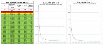
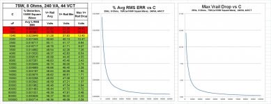
Anyway, these are all cases where the size and ratings of the transformer should NOT come into play. They are 25W, 50W, and 75W supplies, each with two 240 VA 44VCT transformer secondaries.
I plotted the % Avg RMS Error (% distortion?) of the tops and bottoms of the square waves versus the reservoir capacitance, and also plotted the maximum power rail voltage dip versus the reservoir capacitance. The data tables are also included.
I have marked the absolute-minimum capacitance (which depends on the amplifier circuit) with yellow highlighting. But other than that I have not tried to find any pattern or rule for the capacitance. So make of it what you can...
The square waves use double the rated power of the supply and have the same PEAK voltage as a sine at the max rated power, which was found to be a good worst-case test for finding the absolute minimum usable reservoir capacitance for a max-power sine wave that could have any phase angle and thus any timing, relative to the charging pulses.
Anyway, these are all cases where the size and ratings of the transformer should NOT come into play. They are 25W, 50W, and 75W supplies, each with two 240 VA 44VCT transformer secondaries.
I plotted the % Avg RMS Error (% distortion?) of the tops and bottoms of the square waves versus the reservoir capacitance, and also plotted the maximum power rail voltage dip versus the reservoir capacitance. The data tables are also included.
I have marked the absolute-minimum capacitance (which depends on the amplifier circuit) with yellow highlighting. But other than that I have not tried to find any pattern or rule for the capacitance. So make of it what you can...
Attachments
Last edited:
Hi Nico, some updates on the 1DIFFQC
http://www.diyaudio.com/forums/solid-state/219354-1diffqc-amplifier-2.html#post3166048
Harrison, would you quantify their individual results so that it can be used as a measure here, I think the first oscilloscope traces from Routhun at http://www.diyaudio.com/forums/solid-state/198500-symef-amplifier-80.html explains a whole lot, if there are others that could provide the same a very definite conclusion can be drawn.
Besides that I have been lurking in the dark shadows on your thread to see what is brewing, out of pure interest for where it is going and I would not miss the all revealing formula for anything in the world.
I am not joking - there are those who can successfully market any product and this may be one golden method so I am not laughing at the back of your head. Not yet anyway.
To minimise inductance there is the technique outlined by jneutron here. The idea is to make the location of the average forward current coincide with the average return current.
With power and ground planes, that happens "automatically", as long as nothing is accidentally put in the way.
Or, if I were doing it with traces or wires, I would just keep them over/under each other (on opposite sides of a PCB), or very close to each other if opposite sides of the board wasn't possible, or twisted together in the case of wires.
Tom, I take it that you promote the idea of the caps be used as in a star ground, or am I miss understanding it. In such a case one would be saddled with several LRC circuits.
Two distinct possibilities exist in that one is of several hi Q resonators and different frequencies which may easily excite with switching transients and the other that of causing differential currents to flow from different capacitors if the LCR circuits being grossly unmatched.
The first remark may have a positive effect of several narrow filters in parallel actually increases to overall bandwidth and reduces the Q thus suppresses switching transients.
Nico,
"Saddled with" should be replaced with "benefitting from". Then I can agree.
The idea is that by paralleling the caps and the connecting conductors, the L and the R are both reduced and the C is increased, all by significant factors.
The alternative is the original LRC, which has worse characteristics.
What else are you going to do, when the equations say that one decoupling cap and its shortest-possible connections still have too much inductance?
Then the only choice is to parallel several smaller ones, AND the connections, to lower the overall inductance.
Cheers,
Tom
Tom, those graphs reveal a lot of information provided that the observer realises that the output signal (driving the load is fixed) and only the error benefits can be had. Now at what point does the error represent noting more worth pursuing.
From the data you present I would select 6000uF as being overly suitable for all three applications.and will split them into 6 x 1000 uF or even 12 x 500uF, if real-estate is not at premium I would go for 60 x 100uF.
From the data you present I would select 6000uF as being overly suitable for all three applications.and will split them into 6 x 1000 uF or even 12 x 500uF, if real-estate is not at premium I would go for 60 x 100uF.
- Status
- This old topic is closed. If you want to reopen this topic, contact a moderator using the "Report Post" button.
- Home
- Amplifiers
- Power Supplies
- Power Supply Resevoir Size