Nico's example is very frequently reported. The fix is easy (post#1115), but identifying the cause is totally a mystery to me. I wonder what situation keeps happening that slows down the reactiveness of the amp power bypass caps. So, would you say that the muddy blur of the overlarge example was from not responding fast enough for transients? Or would you say that the amp board power caps lost the competition for charge?The RC time constant is not a problem, when charging the decoupling caps on the amp board. You're thinking of the slower exponential decay of a larger capacitance's voltage, as it discharges current through a resistance. But look at the very beginning of that curve. There is no slow ramp UP to it. The current starts flowing blindingly quickly, and at its highest rate.
The power rails themselves do have resistance and self-inductance that could slow down the charging of the decoupling caps. But larger reservoir caps should only help make it faster and better for the decoupling caps, as far as I can see.
Question:
Did my schottky in post 1115 work by providing voltage drop, or did they work by preventing the charge from coming back out of the amp caps?
Last edited:
HOWEVER, that job, the "fast" part of it at least, will be handled by the DECOUPLING CAPS, which HAVE to be very near the points of load (to be fast-enough), not by the reservoir caps.
")
and big enough to make it on their own
fortunately they are getting bigger these days
what is a transient anyway ?
many think of it as a small exstra signal
I would rather say its the full signal, plus some exstra
which is why I say the last cap should be big enough to make it on its own, basicly
Seriously, "transient" is EVERYTHING that is not "steady state".
steady state doesnt sound like music to me
are you talking about test bench measurents ?
Hi Daniel what is the switching frequency of mains
i am not daniel, but each time i read the word "switching", digital circuits comes to mind, you know, the on/off thing on the +5v dc rails.....
"mains" is of course the power line voltage, it is ac and crosses over a zero ref as polarity of the wave reverses......
some convention needs to be agreed upon i think....
steady state doesnt sound like music to me
are you talking about test bench measurents ?
it is not, and it's boring, who would want to listen to a 60hz sine wave played on the speakers.....
i am not daniel, but each time i read the word "switching", digital circuits comes to mind, you know, the on/off thing on the +5v dc rails.....
"mains" is of course the power line voltage, it is ac and crosses over a zero ref as polarity of the wave reverses......
some convention needs to be agreed upon i think....
Mains frequency.
,
Last edited:
THE transient you have to worry about in a music signal is when the waveform has a very short rise time, a sharp slope so to speak. This is hard work for everything: ESR, ESL of the caps, the PSRR and FB circuit of the amp are severely tested by this, separates the men from the boys ...
As an example of how bad that "transient" music signal can be, the following is about as rough as it gets, I reckon. This is an excerpt from a real music track, bizarre as it seems, Iggy Pop and the Stooges, Raw Power album, "I Need Somebody":

But, the funny bit is, only the top waveform is one channel from that album, the bottom track is a 2.2kHz sine wave generated by me, that's been amplified 10dB beyond clipping!! Hmmm, this is getting mighty close to a square wave, available on a music track - now, just set this on A-B repeat, and uuup the volume ... !
Frank
As an example of how bad that "transient" music signal can be, the following is about as rough as it gets, I reckon. This is an excerpt from a real music track, bizarre as it seems, Iggy Pop and the Stooges, Raw Power album, "I Need Somebody":
But, the funny bit is, only the top waveform is one channel from that album, the bottom track is a 2.2kHz sine wave generated by me, that's been amplified 10dB beyond clipping!! Hmmm, this is getting mighty close to a square wave, available on a music track - now, just set this on A-B repeat, and uuup the volume ...
!Frank
Last edited:
Seversal people have raised the issue of larger caps sounding worse. Various possible explanations:
1. They are actually better (i.e. more accurate) but some people don't like accurate as they find it boring.
2. Large caps can cause more induction of charging pulses into signal circuitry if layout or grounding are poor.
3. A large cap might not be able to fully charge during the charging pulse so the extra HF headroom provided by a smaller cap is lost. Smallish caps means that an amp which can do 100W bass might be able to do 120W treble immediately after the bass note. Huge caps may mean that it takes a few mains cycles to recharge so any big HF transient in that period gets clipped.
A cap can't charge and discharge at the same time, but it never has to. It simply takes the net current in or out and uses that.
OK, very rough estimate coming up: assume transformer effective secondary resistance is about 0.1ohm. Charging period is about 2ms, so we want the CR time constant to be less than 1ms to give a reasonable amount of charging. So C < 10000uF. You can do the sums for your transformer. A cap bigger than this will begin to bring the HF transient power down to the LF transient power, and will in a sense introduce 'memory': max power will depend on what the music has just done in the previous few 10's of ms. This effect will not show up in 'normal' amplifier tests, but you could construct a test signal to show it.
So provided your amp has sufficiently good PSRR (use secondary smoothing as well as good circuit techniques) there may be a case for not using too big caps. As I keep saying, calculate the minimum then double it. Very conveniently, the minimum seems to come out as single-figure mF, and the maximum seems to be double-figure mF, so just choose high single-figure or low double-figure mF i.e. 5000-15000uF. This is for domestic amps. PA is bigger!!
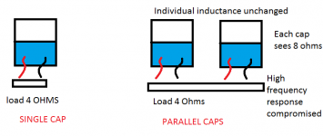
Might be fun, but wrong. HF performance is improved by paralleling caps, not compromised. Each cap sees half the load, as the picture said. This halves the time constant, so doubles the rolloff frequency. Remember, for LR circuits the time constant is L/R so bigger R means faster response - the opposite to CR circuits.OnAudio said:Fun stuff about parallel caps
Attached Thumbnails
Power Supply Resevoir Size-parallel-caps.png
Hi all,
...then perhaps we might include in our reasoning heat and aging related effects. I bet some wiser than me already posted the following, anyway I found this interesting for me: www.vishay.com/docs/49663/49663_pl0359.pdf
It seems that our rule of thumb estimation should be parametrized to heat condition and age... so basically, how long we like to keep and listen to our amplifier.
Ciao,
Stefano
Last edited:
Not quite, the slope corresponds roughly to that of an unclipped 8kHz sine wave; if you look closely at the waveforms you can see 2 or 3 data points on each vertical section. Maximum slew rate would be one data point at full negative excursion, and the next at full positive excursion, something that could be created in a program like Audacity.Hi Fas,
can you tell if that upper trace (CD music sample) is approaching the maximum slew rate available from CD's 44.1kS/s?
Would that be related to a 20kHz signal slope? And of what amplitude?
This would correspond to a maximum amplitude, near enough 20kHz signal, which could be recovered with better than -90dB distortion. Correctly behaving digital is remarkable stuff ...
Frank
- Status
- This old topic is closed. If you want to reopen this topic, contact a moderator using the "Report Post" button.
- Home
- Amplifiers
- Power Supplies
- Power Supply Resevoir Size