GooTee,
Bravo on your dedication and defining the situation in a way that anyone should be able to understand. Take the night off and we expect all the answers tomorrow..... Just kidding.
I think that you have very concisely stated the problem and what needs to be done to answer the questions. I myself am impressed with your effort and work.
Steven
Thank you, very much, Steven.
I might argue with your definition of "concise". <grin> But I think that sometimes it's good to try to regain our awareness of some type of "frame of reference". Or maybe I'm the only one who needs that. <grin>
Does anyone want an explanation of how the simulation's marker voltages and measurement commands work? (Be careful about what you wish for. <smile> [Actually, although it looks a little "hairy", it wasn't that bad and just sort of fell together in about an hour or two, AFTER I finally figured out how the TRIG and TARG statements were supposed to work.])
Regards,
Tom
Last edited:
I'm going to go listen to some music, with my incredibly-wonderful Magnepan speakers.
Every time I hear them, it's almost as exciting and awe-inspiring as touching a woman for the very first time.
Well, not really. But they are exquisitely-great. And I just want to keep doing it, again and again.
Cheers!
Tom
Every time I hear them, it's almost as exciting and awe-inspiring as touching a woman for the very first time.
Well, not really. But they are exquisitely-great. And I just want to keep doing it, again and again.
Cheers!
Tom
Tom, sorry I haven't been more active lately, you know, life and all that! Anyway, I had a play with your pulse source, but what I did just to make things fair to the circuit was to drop the slew rate to that equivalent to a 20kHz waveform: made rise and fall times 20usecs. This is as nasty as one can encode a CD, so theoretically, if Iggy Pop had another go at mastering, this could end up in the stores! The end result? Double the power dissipated in the load, 200W, so the answer is, yes. And not that much worse voltage sag.So, DF, Terry, Fas, and other experts: Square-wave testing, with peak values equal to the peak sine values previously used, as in post 846, should be comparable to using a sine load current's or voltage's peak value instead of its RMS value, as the DC load current or voltage when calculating ripple and the needed reservoir capacitance using the standard approximate formulas, correct?
So it's like using double the power as a worst-case design margin, and throwing in huge fast transients, too.
But what would be worth playing with now is ESR: at full power the voltage sag varies dramatically once you go over 30mR. This is where the parasitics really start to intrude very significantly, may be much more important than the nominal capacitance.
Frank
Last edited:
Tom, sorry I haven't been more active lately, you know, life and all that! Anyway, I had a play with your pulse source, but what I did just to make things fair to the circuit was to drop the slew rate to that equivalent to a 20kHz waveform: made rise and fall times 20usecs. This is as nasty as one can encode a CD, so theoretically, if Iggy Pop had another go at mastering, this could end up in the stores! The end result? Double the power dissipated in the load, 200W, so the answer is, yes. And not that much worse voltage sag.
But what would be worth playing with now is ESR: at full power the voltage sag varies dramatically once you go over 30mR. This is where the parasitics really start to intrude very significantly, may be much more important than the nominal capacitance.
Frank
No worries, Frank.
The maximum slew rate of a sinusoid will depend on the peak-to-peak amplitude. For a +/-40V sine, the peak slew rate occurs at the zero crossings and is about 5 volts per microsecond. So that rate should also be able to be sustained from peak to peak, which should be able to be encoded even on a bandwidth-challenged CD, in a triangle waveform. Remember that after amplification, the slew rate can be much higher than what's in the same signal when at line-level. Anyway, at 5 V/us it would only take 16 us to go from -40 to +40 Volts.
That will certainly make it easier to do the decoupling.
Ah yes, that generic capacitor model. It's been in the back of my mind the whole time, making me wish I would take a closer look at it. It was just a quick-and-dirty convenience when I first started using it.
What I should probably try to do is get a complete series of values of the frequency-dependent cap models from the Cornell Dubilier site and somehow set them up in a subcircuit so that the desired value cap would be connected automatically, so I could still do the automated sweeps of capacitance values.
Last edited:
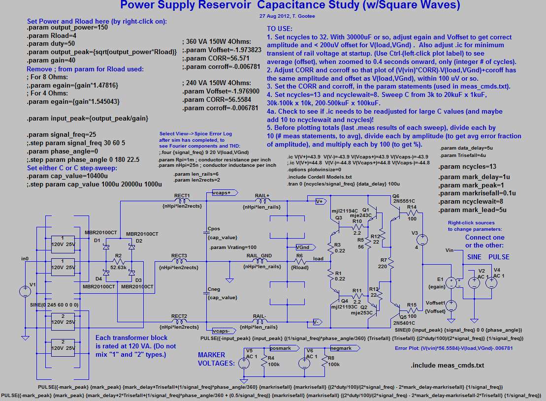
Here are the files for simulating with square waves.
I hope I didn't leave out anything important.
(These should still work with sine waves, too, but you'd probably want to at least un-comment the .four command and comment-out (with leading semicolon) the meas_cmds.txt "include" statement.)
At some point, I need to go in and set it up with someplace where binary values are set, to select the configuration, and everything else is set automatically, maybe using the u() unit-step function of each binary parameter multiplied by each alternative value and then all of them could be summed, so that the one selected would be multiplied by 1 and the others all by 0, so the sum would be the correct value for the selected case.
Cheers,
Tom
Attachments
Last edited:
Oh, awesome! If given a fairly big transformer, 5400uF is the minimum capacitance that works okay with the 150 watts. That totally makes sense.It says 150 Watts PER RAIL (i.e. per voltage rail; one positive and one negative, for a total of 300 Watts if BOTH rails are operating). The RMS Power (dissipated in the load) of the square wave is done as if the negative portion were folded around the axis to be positive. With only one rail, the negative parts would be missing so the power would be half of the total given (half of 300 W).
I have observed that the standard/economy power caps are much more successful upon power supply boards than high efficiency (low esr) caps. To get the same bass, it takes a huge amount more of the high efficiency (low esr) caps than it would the standard/economy caps. And the only thing more astonishing than the effectiveness difference is the price tag difference which is a bit counter-intuitive. Is it because the slightly more lossy (ordinary) cap is a more effective noise filter?But what would be worth playing with now is ESR: at full power the voltage sag varies dramatically once you go over 30mR. This is where the parasitics really start to intrude very significantly, may be much more important than the nominal capacitance.
Big "local" cap near output device
@ Tom: thank you for your kind feedback. It wouldn't make sense to me either, but I have to build in order to get hands-on experience and be more confident on my impressions/thoughts.
@ Nico, Michael (MiiB): I found the quoted post of yours. Did any of you ever build that amp?
One could generalize the thread to Power Supply Reservoir Size and Place ...
...
Stefano
Tom,
About two years ago MiiB (Michael) and I was exchanging ideas on an amp design and he came forward with a PCB layout that had a reservoir cap of 10000uF between each power device. i.e. there was a large cap sitting a few mm from the active device.
I thought this was quite a novel idea at the time. I have not tried it in reality but it seems to tally with what you are promoting here Tom. It may not only be what is in the power supply but how it is distributed that makes the difference.
@ Tom: thank you for your kind feedback. It wouldn't make sense to me either, but I have to build in order to get hands-on experience and be more confident on my impressions/thoughts.
@ Nico, Michael (MiiB): I found the quoted post of yours. Did any of you ever build that amp?
One could generalize the thread to Power Supply Reservoir Size and Place
...Stefano
To add a bit more meat to what I said before about the ESR of the smoothing capacitor, here is what happens to the voltage rail when Tom's model is driven by a full power 1kHz sine wave into 8ohms, for 2 different values of the ESR, 30mR and 300mR, nothing else varied:

Hopefully what you're for using on your amp are around 30mR or better, but if they're a bit dodgy or long in the teeth then the other value may be closer to what you have ...
Frank
Hopefully what you're for using on your amp are around 30mR or better, but if they're a bit dodgy or long in the teeth then the other value may be closer to what you have ...
Frank
Looking at that last post of mine, what you're saying doesn't make sense at first glance. But this whole power supply linking with circuit with associated parasitics thing is a can of worms, I believe; every case is different, and quite a bit more delving will be necessary to fully understand all the aspects that impact the final, perceived sound ...I have observed that the standard/economy power caps are much more successful upon power supply boards than high efficiency (low esr) caps. To get the same bass, it takes a huge amount more of the high efficiency (low esr) caps than it would the standard/economy caps. And the only thing more astonishing than the effectiveness difference is the price tag difference which is a bit counter-intuitive. Is it because the slightly more lossy (ordinary) cap is a more effective noise filter?
Frank
Frank,
Could you repeat the sim with an added 100mR in series as per a typical C-R-C supply - very informative picture with the current charging pulses so clearly shown - is there any provision to show the diode turn-off reverse spike so might be able to extend the model to show the behaviour of a typical Hagerman snubber, etc ...
Could you repeat the sim with an added 100mR in series as per a typical C-R-C supply - very informative picture with the current charging pulses so clearly shown - is there any provision to show the diode turn-off reverse spike so might be able to extend the model to show the behaviour of a typical Hagerman snubber, etc ...
I have some approximate equations for the simplest case, in which the transformer series resistance R is sufficiently low that the CR product (C is reservoir cap) is significantly shorter than the available recharge time so the cap more or less fully recharges each half-cycle. This would roughly correspond to standard engineering design, I think. Still working on the case where R or C is higher. Very high C roughly corresponds to 'modern' or 'audiophile' design, where if C is good then 100C 'must' be better.gootee said:So hey, DF96 (or anyone): "Got equations?"
I would consider this type of sim is more appropriate to modeling the amplifier and examining the PSRR and such............very informative picture with the current charging pulses so clearly shown - is there any provision to show the diode turn-off reverse spike so might be able to extend the model to show the behaviour of a typical Hagerman snubber, etc ...
Not here where we are looking at a different effect.
Frank,
Could you repeat the sim with an added 100mR in series as per a typical C-R-C supply - very informative picture with the current charging pulses so clearly shown -...
Jameshillj,
The "load-current pulses" very-often have a greater effect on the rail voltage than the charging-current pulses.
You might have been looking at the effects of the load-current pulses (unless you're looking at the only two wide ones, wich are centered at roughly 88.5 ms and 97 ms; those are the effects of the charging pulses). The load current pulses cause the rail to drop. So the "downward-pointing" voltage spikes/pulses are caused by the load-current pulses that the transistors are allowing to flow out of the positive rail.
Check the time scale at the bottom. The faster-occurring pulses are 1 ms apart, i.e. 1 kHz. And he said he applied a 1 kHz sine signal that gave the maximum output amplitude.
...is there any provision to show the diode turn-off reverse spike so might be able to extend the model to show the behaviour of a typical Hagerman snubber, etc
Wow, man, you really need to download LT-Spice (free from linear.com). You don't need additional "provisions", to look at something. You can show almost ANYTHING.
The mouse pointer instantly turns into a PROBE(!) as soon as it moves over the schematic, which I posted just a few posts back, and which is also at http://www.diyaudio.com/forums/atta...wer-supply-resevoir-size-schematic_square.jpg .
And with a quick right click on a wire and then a left click on a pop-up menu, you can set the probe reference point anywhere you want, if you don't want it referenced automatically to ground.
Also, moving the probe over the top of a two-terminal device, or to a pin of a multi-pin device, changes the probe into a CURRENT probe.
Click whatever or wherever you want on the schematic and it's instantly plotted. Watch the plots unfold as the simulation time progresses, if you're simulating in the time domain. But it's just as easy to switch to the frequency domain.
Note that there IS a snubber in the circuit, already (but not aimed specifically at the turn-off spike): R2 is the snubber. The optional C in series with it was unnecessary in this case because the optimal dampng resistance was so high that its dissipation was low-enough that no frequencies needed to be restricted from it, making the optional series C unneeded.
The snubber was needed in an earlier version of the circuit in order to damp out a very strong and persistent ringing that was at a fairly-low frequency (below 1 MHz). I can't remember the details, right now. But the circuit changes whenever the transformer model is reconfigured or the reservoir capacitance is swept.
When simulating, I usually only bother with designing a snubber if it is needed in order to prevent the sim from slowing to a crawl. I haven't checked this one without the R2 installed, lately, but it's a high-enough R value that I just left it in.
By the way, that snubber was designed by using the steps I posted at:
http://www.diyaudio.com/forums/powe...lm-caps-electrolytic-caps-30.html#post2828689
(I realize that the snubber looks a little weird, with such a large R value. But it did work extremely well.)
I have seen an almost-identical snubber-design method in several different papers, and also in some other places, on the web. I read Jim Hagerman's snubber stuff "a few" years back, along with a lot of other snubber materials, but I can't remember if his method was similar. Anyway, did he invent a special case or type of snubber, since then? (Otherwise I would have to wonder why snubbers should be named after him.)
Regards,
Tom
Tom & Frank, I am sorry I have run out of nice things to say. But be aware I have not missed a single post nor missed making notes that I feel could eventually be helpful in the conclusion or dying posts in this thread. Thanks again guys.
I have laid a little headphone amp board to the test the "sonic" effect of multiple smaller caps as I am currently using the same amp with a single cap per rail.
I feel headphones are the best test system because you have some of the worlds best speakers only a centimetre from your ear and no room acoustics or furnishings or any other obsticle to affect what you hear.
Attachments
Thanks Tom, my old CRO has trouble producing such clearly defined signals with all the diode and supply line hash messing up the picture - I see the loading influence and it still surprises me to see how much the rail is modulated with the input/output signal of the F5 classA amp, for example, and the different effects of various capacitors types and sizes in the power supplies.
You're right, I'll have to have another go at sorting out the LT Spice tool - my computer skills are limited and interpreting the results require skill and knowledge that is sadly lacking here - very much appreciate your, and everyone else, detailed info.
Jim Hagerman was the paper "of my day" and just about everyone that is interested in snubbers in "hifi land" has at least heard of it, so it's a 'sort of' reference - as you say, many other studies and papers around - don't think there's been any further developments except better definition/recognition of the problems, particularly in conjunction with the falling quality in power distribution and transformer quality.
A bit off subject, did you complete your version of George's Lightspeed Vol Control a few years ago, and if so, how did it work out?
Thanks for clarifying things, Tom; trying a C-R-C variation of the type suggested by james would show nothing, because its impact would be swamped by the presence of other behaviours.
This whole business is an intricate dance, participated in by the non-perfect behaviour of the mains, the parasitics of the power supply, the PSRR of the circuit driven, and finally the typically complex impedance of the speaker load. There are no straight answers here, which is why when people start fiddling with things in this area the sound quality changes ...
Frank
Thanks for clarifying things, Tom; trying a C-R-C variation of the type suggested by james would show nothing, because its impact would be swamped by the presence of other behaviours.
This whole business is an intricate dance, participated in by the non-perfect behaviour of the mains, the parasitics of the power supply, the PSRR of the circuit driven, and finally the typically complex impedance of the speaker load. There are no straight answers here, which is why when people start fiddling with things in this area the sound quality changes ...
Frank
<rant>Ten minutes of typing a reply just %$#&%$# disappeared! (And yes, I know about Undo, and Ctrl-Z and Ctrl-Y, and Back and Fwd, and I usually periodically do a Select All and Copy.) Shouldn't there at LEAST be a &%$%#@ keyboard buffer, or SOMETHING, that allows one to get back what they have just typed?!</rant>
Anyway, yes, it's deceptively simple-looking, which has been mentioned in every one of the papers I've read where they derive the "real" equations for the "simple" transformer, rectifier, and capacitor circuit. It always ends up being many PAGES of complex integral and differential equations, with many transcendental functions in them, and also seemingly always some integrals that "have no closed-form solution". And none of the ones I have found has even attempted to include an active load.
If I ever get around to it, I will probably try to just substitute every transcendenal function with its Taylor Series Expansion, which turns everything into polynomial forms that can be made as accurate as needed by just adding on higher-order terms. That way, everything would be trivial to integrate and differentiate and we would end up with a system of polynomial equations that would be a true model (or "true-enough", at least), and could be crunched by any spreadsheet software. We could even get things like three-dimensional plots that could bound the usable values of several variables after others were already chosen, for example. The possibilities are almost endless, and very attractive.
Anyway, speaking of "...the sound quality changes", our model does have the capability, right now, of varying things (either automatically or manually) and then looking for resultant values or changes or conditions in the output signal.
And if we use WAV files for both input and output, we can COMPARE the input and output files to each other, or compare pairs of output files to each other, automatically, using software like diffmaker (a free download).
AND, we can also LISTEN TO the output files!
BUT, we don't know a lot about WHAT to measure, from within spice simulations, for example, in order to be able to predict "sound quality", unless it would just be something like looking for the minimum sum or average of the arithmetic differences between output and input WAV files or voltage plots. The calculated THD could be helpful but (I think) we think we know that low THD alone is not a good predictor of sound quality. Maybe it's "necessary but not sufficient". (But it is "easy". Right now, tonight, you could do things like generating plots of THD versus capacitor ESR or ESL, for example, or anything else in the model.)
So, anyway, I can envision a scenario where, initially, someone could be cranking-out WAV files, with LT-Spice simulations, and sending them to a team of volunteer "listeners", who could somehow rate them for "sound quality".
That might eventually enable someone to discover some measurements, or, maybe more-likely, even just simple configuration or parameter changes, that DO correlate with sound quality. That information could then be used to better-inform design-parameter choices/tradeoffs, or optimization schemes, etc etc.
A lot would probably depend on the sequences of what was tested and rated. There are people here, like SY, who seem to know a lot about the proper design of "human-based rating systems". But, as a first guess, think about when you go to get eyeglasses: They use a sequence of "binary" choices, where you are always rating which is the better of only TWO options at a time, and you eventually converge on the best one. (It's the old familiar "binary tree" concept that is/was used so much in things like database search algorithms.) But WHAT was to be compared and rated would still need to be determined. Yes it could be complex and difficult to design that part of the expriment. But it could also generate quick successes. And there is already a large framework of opinions and ideas available.
I could continue to make-it-up-and-elaborate-as-I-go, but that's all just a sleepless dream, at this point, anyway. However, it might be the beginning of finding a way to "leverage" some capabilites (i.e. 1. automation using simulation: cheaper, faster, and more repeatable and controllable than alternatives, and 2. cooperative efforts of many people, using the internet to quickly and easily send out the test files and receive the results) in order to greatly speed-up the process of developing some understanding and some methods that could be useful in improving everyone's ability to repeatably generate better audio system designs.
I'm not quite sure how I managed to diverge to that point. Oh well.
Later,
Tom
Last edited:
I feel headphones are the best test system because you have some of the worlds best speakers only a centimetre from your ear and no room acoustics or furnishings or any other obsticle to affect what you hear.
if the recording is binaural, hells yeah! If it is a normal recording, not so much.
Not a bad effort after being thoroughly p***ed off by the joys of normal IT engineering, Tom! I feel for you, having been there many times before, it's always the pieces where one puts a lot of energy and enthusiasm into it that go down the gurgler ...
I might invent a new phrase, something along the lines of ... "Tomorrow is another day!". How do you reckon that'll go down ...?
Frank
I might invent a new phrase, something along the lines of ... "Tomorrow is another day!". How do you reckon that'll go down ...?
Frank
- Status
- This old topic is closed. If you want to reopen this topic, contact a moderator using the "Report Post" button.
- Home
- Amplifiers
- Power Supplies
- Power Supply Resevoir Size