line filters
Some line filters from Digikey
15EH4 TE Connectivity | 15EH4-ND | DigiKey
15SRBS1-X TE Connectivity | CCM1783-ND | DigiKey
Some line filters from Digikey
An externally hosted image should be here but it was not working when we last tested it.
15EH4 TE Connectivity | 15EH4-ND | DigiKey
An externally hosted image should be here but it was not working when we last tested it.
15SRBS1-X TE Connectivity | CCM1783-ND | DigiKey
This type of setup should also be a very good starting point for getting some kind of comparable measurements of transient responses, that could be used when investigating and characterizing the effects of varying decoupling capacitance.
Cheers,
Tom
Looking forward, you did say tonight

Gootee well, I have curiosity to see the behavior, the response of the psu on transient current, time to balance and voltage drop. with all due respect for the work you have done, I am very skeptical about the result (in relation to what are my studies,then what I want ). 50 / 60Hz create a hole of energy, it would be easy to keep it on a choke, but this is not an acceptable solution.
I solved electronically as "nesis-regulator" but with a switch engine. at end, total weighs 400 grams, absolute clean fft, 2.7 V voltage drop on 600w burst. .. not bad.
I solved electronically as "nesis-regulator" but with a switch engine. at end, total weighs 400 grams, absolute clean fft, 2.7 V voltage drop on 600w burst.
.. not bad.Hi,
a big thank for letting me grab at least something about the discussed and deepened subjects.
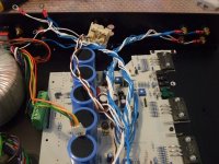
I was just planning to add more capacitance to a power amp of mine while substituting a faulty lytic in the psu (there are 8 of them for 80mF total), but I think I have learned this is not the case
So, I'll try to add the extra local smaller capacitance "kit" as near as possible to the output pair used (Sanken 2SC2922 and 2SA1216 for each channel).
Looking at my drawer I found a bunch of Elna 330uF/100v around and was thinking of paralleling 4 or 5 of them, bypassed with 0.1uF and, perhaps, with another 0.056/400 for each rail.
Thanks again for sharing your hard work and knowledge with whom is absolutely aware not to know (Tsiros, forgive should the quote be not 100% correct )
Keep up the good work,
Stefano
a big thank for letting me grab at least something about the discussed and deepened subjects.
I was just planning to add more capacitance to a power amp of mine while substituting a faulty lytic in the psu (there are 8 of them for 80mF total), but I think I have learned this is not the case
So, I'll try to add the extra local smaller capacitance "kit" as near as possible to the output pair used (Sanken 2SC2922 and 2SA1216 for each channel).
Looking at my drawer I found a bunch of Elna 330uF/100v around and was thinking of paralleling 4 or 5 of them, bypassed with 0.1uF and, perhaps, with another 0.056/400 for each rail.
Thanks again for sharing your hard work and knowledge with whom is absolutely aware not to know (Tsiros, forgive should the quote be not 100% correct
)Keep up the good work,
Stefano
OnAudiooo,
There is a major difference in price between the two AC filters you show from DigiKey. What is so different about them, they both seem to be RF filters on the AC input. Would this replace an X-capacitor across the transformer or is this in addition to that?
The X cap still remains. If you look at the datasheets,the more expensive one features chokes. (and is classified as medical grade) . It is possible that there are filters that already incorporate the X cap at the connection to the transformer, in such a situation then the X cap is already in the filter.
kind regards,
Harrison.
You can have a look at this document http://www.epcos.com/web/generator/...erty=Data__en.pdf;/PDF_EMIGeneralStandard.pdf
Adding such items willy nilly to a system may or may not have an overall benefit. Sometimes it may degrade: unless the elements are analysed in the context of a complete electrical circuit, by simulation or whatever, taking into account the true quality of the mains coming through, which is normally rather nasty, to finally reach the voltage rails of the component then to a large degree you're wandering in the dark ..Some line filters from Digikey
Frank
OnAudiooo,
There is a major difference in price between the two AC filters you show from DigiKey. What is so different about them, they both seem to be RF filters on the AC input. Would this replace an X-capacitor across the transformer or is this in addition to that?
I always use these on everything. I've seen prices for $1 up to $15 and there is not much difference in quality. But do look at the Amps rating. You want to buy the filter that has the LOWEST rating but can still handle the expected current. In other words do NOT "over spec" these. Why? The smaller rated filters better attenuate the noise. Just read the specs.
BTW I salvage these from old CRT computer monitors. Lots of good parts in the larger size monitors and these are now "toxic waste" so they are easy to get.
Kindhornman @ #803, OnAudio @ #801:
these two filters are quite different. The top one (15EH4) is a combined Common-Mode/Differential-Mode filter, whereas the bottome one (15SRBS1) is a Common-Mode filter.
Common-Mode: noise currents carried equally by phase & neutral, returning along the Protective Earth wire.
Differential-Mode: Noise currents flowing down the Phase wire, returning via Neutral. No current in the Protective Earth wire. Load Current drawn by the amplifier is DM.
The 15EH4 has a common-mode inductor in series with P & N. Load current flows into P and out of N, and so the resultant fluxes cancel in the CM choke and it does nothing - unless the CM choke has imperfect coupling, in which case there is a bit of DM inductance too (this is often done deliberately). The CM choke leakage (if any) and the X-capacitance form a DM low-pass filter.
The 15SRBS1 filter is a first-order CM filter, as all it has are a pair of "Y" caps connected to PE. It wont do anything to DM noise.
Aside: an LC filter (L on line side, C on load side) is a voltage LPF, filtering AC line voltage noise. If you look at it backwards (from load side) and drive it with a noise current (generated by the load) it is still a low-pass filter - the C turns the noise current into a (hopefully smaller) noise voltage, which is dropped across the L (if any) that then (again hopefully) reduces the resultant noise current flowing back to the AC line.
I've done a lot of work on EMI filtering, as SMPS generate a horrendous mess that must be cleaned up - both CM and DM noise. But I've never measured the EMI performance of an audio amplifier, so herewith some guesswork.
Unless the amplifier has some nasty oscillations, the DM "noise current" presented to the bridge rectifier will be the audio output current, with its spectra suitably modified by the DC bus cap/wiring.
But the rectifiers themselves can and do generate HF noise when they stop conducting - the diode snap-off excites oscillations in the LC circuit comprising the transformer secondary leakage and the diode capacitance. This is why rectifiers often have caps (usually 100nF) connected across them, although this is NOT the right solution - it doesnt alter the damping much (if at all) but just moves the resonant frequency. The correct solution is to use RC dampers across the diodes.
The bridge rectifier also converts some DM noise into CM noise, for esoteric (read as: I forget why) reasons.
The transformer primary-secondary capacitance also helps generate CM noise at the mains input by converting some secondary DM noise into CM.
the real problem with EMI is its BW - noise measurement standards (other than military) start at 150kHz, and go up to 1GHz or more (Audio amps will have a 1GHz upper limit, unless they contain a micro with a clock > 125MHz, which I doubt, in which case it will be 3GHz).
And above about 5MHz, the EMI performance is dominated by parasitics - IOW layout.
A typical EMI filter is a "PI" filter - X cap, CM/DM choke & X cap. above 10MHz the filter insertion loss is dominated by the mutual inductance between the two X caps, which are invariably oriented in parallel. there is a good reason this stuff is referred to as "black magic" (even though it is not). To make matters worse, it is nigh on impossible to measure anything, as the simple act of attaching a probe changes everything.
one thing is for sure - the construction methods typically employed at audio frequencies are utterly useless for controlling EMI. There are some really good books on this stuff - Henry Ott being one of them. Remember: Current Flows In Loops - Minimise Them.
In an audio setup, Terry, it's very easy to measure what's going on, just use your ears! Once a system is working to a decent quality level, the slightest variation is filtering and EMI behaviours is blindingly obvious, as the treble quality changes markedly - the clarity of the upper spectrum improves with each change, movement in the right direction.To make matters worse, it is nigh on impossible to measure anything, as the simple act of attaching a probe changes everything.
one thing is for sure - the construction methods typically employed at audio frequencies are utterly useless for controlling EMI. There are some really good books on this stuff - Henry Ott being one of them. Remember: Current Flows In Loops - Minimise Them.
Also, mobile phones are very useful and portable test devices: excellent EMI rejection is indicated if there is no change of treble tonality between phone switched on, or off.
Frank
Frank, I dont think I'd consider "listening" to be a very good measurement. Although I have done it when tracking down a self-interference problem. A cellphone wasnt grunty enough so we used a 40W CB transmitter sitting next to the DUT - CW Tx interfered badly enough that the smps output rose, and we could hear the change in fan speed. The culprit? a loop. the fix? cut either end of an 0V trace, and re-run it with Kynar.
If you can audibly detect the difference between AC line EMI filters, I can think of only two possibilities - unbelievably appalling construction, or experimenter expectency. The latter is a serious problem when troubleshooting EMI. I dont consider a problem "fixed" until I have made it go away and reappear a few dozen times, spread over a few days.
with enough practice, one simply looks for the known culprits - lousy PCB layout & lousy wiring practices are right at the top of the list. loops can be tricky to spot in multi-pcb assemblies, but are often there.
Wiring methodologies are almost always neglected at the design stage. e.g. a small ribbon cable with say 8 x signal, Vcc & 0V. smart designers place the 0V trace in the middle, surrounded by the data traces with Vcc tossed in later (supply rails can and should be filtered heavily, data signals obviously cannot be). Yet this is very seldom done - invariably 0V is at one end of the ribbon cable, thereby maximising all the loops. Cable termination is even more poorly understood, and seldom applied. *sigh*
Terry, I don't mean measurement in the sense of numbers, rather purely to verify that there is a problem or not. And we are talking subtleties here, not the obvious crackling of some EMI breakthrough artifacts. Typically when there is an issue the interference manifests as a dulling, or addition of a slight edgness to the treble ... does that sound like the frequent complaints about digital sound? You betcha!!
As regards making a problem go away and reappear, once the ear is tuned to this type of misbehaviour, it's dead easy to spot. For any number of repetitions of culprit on/off ...
Frank
As regards making a problem go away and reappear, once the ear is tuned to this type of misbehaviour, it's dead easy to spot. For any number of repetitions of culprit on/off ...
Frank
Is there some other form of measurement? Of course, we can sometimes detect changes by ear alone but measurement means numbers.fas42 said:I don't mean measurement in the sense of numbers
Fair enough. I was being a bit loose with language, following in the vein of Terry's comment that readings yielding meaningful numbers are extremely difficult, because the presence of the measuring device itself will generally disrupt the state of what's being detected at these frequencies. At least one's ears are not guilty of that!Is there some other form of measurement? Of course, we can sometimes detect changes by ear alone but measurement means numbers.
Frank
Wiring methodologies are almost always neglected at the design stage. e.g. a small ribbon cable with say 8 x signal, Vcc & 0V. smart designers place the 0V trace in the middle, surrounded by the data traces with Vcc tossed in later (supply rails can and should be filtered heavily, data signals obviously cannot be). Yet this is very seldom done - invariably 0V is at one end of the ribbon cable, thereby maximising all the loops. Cable termination is even more poorly understood, and seldom applied. *sigh*
Terry and all, would you be so kind to provide a couple of good references and/or your findings on proper wiring methodologies (both signal and "power") and termination? Aside from my past University studies I've never heard of the latter applied to audio, with the well known exception of "digital" cables, but the MHz-GHz effects you have described well deserve it!
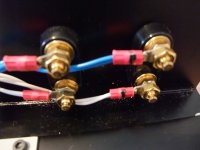
For example, the power amp I'm trying to fix has left and right speaker wires twisted together (where each pole of a channel made of a twisted pair, i.e. two wires of same polarity) and twisted with L and R input wires... this almost shocked me, since going from memory I would place L and R channels as far as possible (and the same between input and output)...
Stefano
Attachments
Last edited:
A ClassA amplifier that does not transition into ClassB and/or does not clip will only bounce back Audio frequencies on the the supply rails. That certainly gives the rectifiers and transformer an easier job. But there are still spikes coming in from the mains and they still give the PSU a real job to do.
- Status
- This old topic is closed. If you want to reopen this topic, contact a moderator using the "Report Post" button.
- Home
- Amplifiers
- Power Supplies
- Power Supply Resevoir Size