You recalling TIM. TIM can occur sometimes but good design amp hasnt it. For a large part TIM is also a hoax. It can occur in not well designd amps but only at such fast and high amplitude transients what never happens in real music.You need to learn that what a circuit does is not always what a circuit wants to do. We're not talking audio signal transients. We're talking regulatory frequency transients caused by non-lineairities in devices. When all is good, the regulatory frequency is very high with minimal swing. When things are not so good you have an amp that's outright unstable and if it's on the edge, it'll be very tacky to listen to.
In the ideal situation there is no regulatory swing, it'll be Vpp=0. BUT as soon as a delta appears in the system, the regulatory swing will be back to adapt to the change in the system. The quicker and faster it can do that, the better the amp is.
If there high frequency regulatory frequencies, whatever it is, what has it to do with the assumed need of high cap? High frequency needs low cap with low parasitic inductance, thats why well design amp has a polypropiline cap paralel to the rectivier Elco.Reading comprehension. We're not talking about the speaker terminal output. We're talking the collector/drain connection points of the output devices. The cap multi is a tool used locally close to the output device power terminals. It's called a "cap multiplier" for a reason. It prevents local sag with a much smaller cap, tapping into the stored current in the PSU buffer caps, though with the nastly L parasitic in between before it gets to your board. The CM transistor actually compensates for the T=0 current draw associated voltage sag.
Wrong. When there is current demand from the amp, without CM, it will draw current from the big rectifier cap. With CM the amp can only draw current from the smaller C at the CM output. The supply will even drop more then without CM.
I never said the crrent did not come from the big rectifier cap. If you refuse to understand and read what people are saying I see no use discussing with you.
I never said the crrent did not come from the big rectifier cap. If you refuse to understand and read what people are saying I see no use discussing with you.
Exactly, no point to try to explain
Thats the typical way to avoid recoqnition of the own fault when it becomes tricky.I never said the crrent did not come from the big rectifier cap. If you refuse to understand and read what people are saying I see no use discussing with you.
The typical response of someone that was deemed not worth the effort.
What is the answer? Its damm tricky hah to get difficult critism from a low level trilingual newbie!? Dan maar afkappen met de goedkope Nederlandse manier. Hihihi...
Exactly, no point to try to explain
Cause there is no explanation, the circuit is useless and even degrading amp performance. Have someone ever seen such a circuit in the power supply of a profesional power amp? No. Does it means that you all are better then those profesionals?
Of course there are harmonics higher then the audio band but there is no need to reproduce that. What do you think is the bandwidth of your source? All are filtered at around 15 to 20 kHz.Your amps must be completely free from any higher order but the fundamental harmonics if you think your transients are limited to the fundamental audio band.
Nico,
its complex, but I'll give it a crack. Caveat - I havent designed any LF transformers (I just specify them and leave it up to the magnetics house I use). I have designed lots of HF transformers and inductors from mW to hundreds of kW.
In a transformer the magnetizing inductance is a parasitic component - ideally it would be infinitely large and draw an infinitely small current. In practice this is far from the case. the question then becomes: how much magnetising inductance do I need? which is better stated as "how much magnetising current can I tolerate".
Reductio ad absurdum - air-cored transformers. these work, and have been used at high power for 50/60Hz. an interesting variant has only the centre leg(s) of the core, but omits all the outside bits of iron. they have two primary disadvantages - they spew flux everywhere, and the magnetising inductance is much, much lower than iron-cored xfmrs. you can make Lmag arbitrarily large by increasing N, but resistance goes up proportional to N (with fixed winding area it goes up with N^2), and leakage inductance goes up with N^2.
efficiency constraints dictate how much power you can waste, setting a limit on (core +) copper losses. so how much Imag? well, lets use 100Vac, 100W as an example. thats 1A. lets do it in Per-Unit (normalised):
Vbase = 100Vac = 1PU Volts
Pbase = 100W = 1PU Watts
Ibase = 1A = 1PU current
w_base = 2*pi*50Hz = 1PU Angular Frequency
Zbase = 100V/1A = 100R = 1PU Ohms
Lbase = Zbase/(2*pi*50Hz) = 318mH = 1 1PU Henrys.
if Lmag = 1PU = 318mH then Imag_pu = V_pu/(w_pu*Lmag_pu) = 1PU/(1PU*1PU) = 1PU
(this is why PU is so handy. we can completely ignore all scaling terms, 2pi*F in particular - so Imag_pu = 1/L_pu when V = V_pu and w = W_pu)
if the transformer supplies 1PU real current and Lmag sucks 1PU reactive current then the input current is sqrt(1+1) = 1.41PU.
Is this OK? maybe yes, maybe no. this is where you have to decide what PU mag current you are happy with. If we had say Lmag = 0.1PU then Imag = 10PU, and |I| = 10.05PU. this is probably an absolutely terrible idea.
whereas if Lmag_pu = 10PU then Imag = 0.1PU and |I| = 1.005PU. this is probably OK, but I will leave calculating the resultant power factor as an exercise (hint: larger PU Lmag = higher PF).
and Lmag = 10PU means Lmag = 3.18H - not an unreasonable number at all.
once you have decided on an acceptable Lmag, you then have two variables to choose - no. of turns and core area. you also have a peak flux density constraint, which depends on the material you pick. assuming some sort of Iron, thats around 1.6T or so.
(magnetisation is the orientation of domains within the material. once they are all aligned, there is no more aligning to be done, and the material is saturated. it then behaves like it is not there. this can be shown easily by measuring the primary leakage inductance of a transformer (sec shorted), then removing the short and measuring the primary inductance WITHOUT THE CORE. and they are the same)
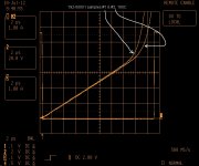
here's the thing though: core materials are non-linear, and typical steels (and ferrites) dont have a sharply defined Bsat (square-loop materials do, but we'll ignore mag-amps here). I like to measure L using a "splat" test - charge a bloody great cap bank to some voltage V, then splat a choke across it and measure Ichoke & Vcap. Vcap = L*dI/dt. assuming C is really big, Vcap ~ constant and for nicely linear materials (eg ferrites) a very straight line results, and L = Vcap*dT/dI
with a ferrite you then get a fairly sharp knee at Bsat, at which point dI/dt skyrockets. as shown in the attachment (PQ26/20 flyback transformer). for less linear materials eg (powdered-)iron, the slope is curvy, but small segments are still pretty straight. and the shift into saturation is much more gradual than shown here - so gradual in fact that it becomes a bit arbitrary. (I do a prestidigitative curve-fit by holding a bit of paper up to the scope, and noting where the trace curves up "too much").
recall the transformer equation: sqrt(2)*Vrms = N*Bmax*Ae*2*pi*Fac
oh god how I hate the V = 4.44NBAF version - it carefully disguises the trivial maths. 4.44 = 2*pi/sqrt(2). this of course derives from V = dLambda/dt = N*dPhi/dt = N*Ae*dB/dt. set V = Vrms*sin(t) and integrate, and out it pops (the cos(wt) is set to 1 for peak flux)
for a given core cross-sectional area Ae, the higher you choose Bmax the lower N becomes. so Lmag gets lower and Imag gets higher, BUT as you move further into saturation, Lmag drops FASTER than expected. this is what gives rise to the strange spiky peaks in the primary current of most unloaded transformers - the core is often saturating quite hard. but it does reduce leakage inductance and copper losses, and save both Cu and Iron. Microwave Oven Transformers push this to absolutely stupid extremes - the first time I repaired a microwave I thought the transformer was faulty, Imag = 6A @ 230V IIRC.
Transformer inrush: the transient application of voltage (say turning it on) can cause the xfmr flux to double - it certainly will if turned on at zero voltage. Any residual magnetism will add to this. for no inrush, just turn the transformer on at peak line voltage (impossible to do with 3 or more phases). Of course that maximises the cap bank inrush......just saying. and of course unless the xfmr is designed for Bmax < Bsat/2 (or has an air gap) the transformer saturates, Lmag plummets and Imag skyrockets. Hence the loud BOING.
its complex, but I'll give it a crack. Caveat - I havent designed any LF transformers (I just specify them and leave it up to the magnetics house I use). I have designed lots of HF transformers and inductors from mW to hundreds of kW.
In a transformer the magnetizing inductance is a parasitic component - ideally it would be infinitely large and draw an infinitely small current. In practice this is far from the case. the question then becomes: how much magnetising inductance do I need? which is better stated as "how much magnetising current can I tolerate".
Reductio ad absurdum - air-cored transformers. these work, and have been used at high power for 50/60Hz. an interesting variant has only the centre leg(s) of the core, but omits all the outside bits of iron. they have two primary disadvantages - they spew flux everywhere, and the magnetising inductance is much, much lower than iron-cored xfmrs. you can make Lmag arbitrarily large by increasing N, but resistance goes up proportional to N (with fixed winding area it goes up with N^2), and leakage inductance goes up with N^2.
efficiency constraints dictate how much power you can waste, setting a limit on (core +) copper losses. so how much Imag? well, lets use 100Vac, 100W as an example. thats 1A. lets do it in Per-Unit (normalised):
Vbase = 100Vac = 1PU Volts
Pbase = 100W = 1PU Watts
Ibase = 1A = 1PU current
w_base = 2*pi*50Hz = 1PU Angular Frequency
Zbase = 100V/1A = 100R = 1PU Ohms
Lbase = Zbase/(2*pi*50Hz) = 318mH = 1 1PU Henrys.
if Lmag = 1PU = 318mH then Imag_pu = V_pu/(w_pu*Lmag_pu) = 1PU/(1PU*1PU) = 1PU
(this is why PU is so handy. we can completely ignore all scaling terms, 2pi*F in particular - so Imag_pu = 1/L_pu when V = V_pu and w = W_pu)
if the transformer supplies 1PU real current and Lmag sucks 1PU reactive current then the input current is sqrt(1+1) = 1.41PU.
Is this OK? maybe yes, maybe no. this is where you have to decide what PU mag current you are happy with. If we had say Lmag = 0.1PU then Imag = 10PU, and |I| = 10.05PU. this is probably an absolutely terrible idea.
whereas if Lmag_pu = 10PU then Imag = 0.1PU and |I| = 1.005PU. this is probably OK, but I will leave calculating the resultant power factor as an exercise (hint: larger PU Lmag = higher PF).
and Lmag = 10PU means Lmag = 3.18H - not an unreasonable number at all.
once you have decided on an acceptable Lmag, you then have two variables to choose - no. of turns and core area. you also have a peak flux density constraint, which depends on the material you pick. assuming some sort of Iron, thats around 1.6T or so.
(magnetisation is the orientation of domains within the material. once they are all aligned, there is no more aligning to be done, and the material is saturated. it then behaves like it is not there. this can be shown easily by measuring the primary leakage inductance of a transformer (sec shorted), then removing the short and measuring the primary inductance WITHOUT THE CORE. and they are the same)
here's the thing though: core materials are non-linear, and typical steels (and ferrites) dont have a sharply defined Bsat (square-loop materials do, but we'll ignore mag-amps here). I like to measure L using a "splat" test - charge a bloody great cap bank to some voltage V, then splat a choke across it and measure Ichoke & Vcap. Vcap = L*dI/dt. assuming C is really big, Vcap ~ constant and for nicely linear materials (eg ferrites) a very straight line results, and L = Vcap*dT/dI
with a ferrite you then get a fairly sharp knee at Bsat, at which point dI/dt skyrockets. as shown in the attachment (PQ26/20 flyback transformer). for less linear materials eg (powdered-)iron, the slope is curvy, but small segments are still pretty straight. and the shift into saturation is much more gradual than shown here - so gradual in fact that it becomes a bit arbitrary. (I do a prestidigitative curve-fit by holding a bit of paper up to the scope, and noting where the trace curves up "too much").
recall the transformer equation: sqrt(2)*Vrms = N*Bmax*Ae*2*pi*Fac
oh god how I hate the V = 4.44NBAF version - it carefully disguises the trivial maths. 4.44 = 2*pi/sqrt(2). this of course derives from V = dLambda/dt = N*dPhi/dt = N*Ae*dB/dt. set V = Vrms*sin(t) and integrate, and out it pops (the cos(wt) is set to 1 for peak flux)
for a given core cross-sectional area Ae, the higher you choose Bmax the lower N becomes. so Lmag gets lower and Imag gets higher, BUT as you move further into saturation, Lmag drops FASTER than expected. this is what gives rise to the strange spiky peaks in the primary current of most unloaded transformers - the core is often saturating quite hard. but it does reduce leakage inductance and copper losses, and save both Cu and Iron. Microwave Oven Transformers push this to absolutely stupid extremes - the first time I repaired a microwave I thought the transformer was faulty, Imag = 6A @ 230V IIRC.
Transformer inrush: the transient application of voltage (say turning it on) can cause the xfmr flux to double - it certainly will if turned on at zero voltage. Any residual magnetism will add to this. for no inrush, just turn the transformer on at peak line voltage (impossible to do with 3 or more phases). Of course that maximises the cap bank inrush......just saying. and of course unless the xfmr is designed for Bmax < Bsat/2 (or has an air gap) the transformer saturates, Lmag plummets and Imag skyrockets. Hence the loud BOING.
Attachments
Last edited:
0h me very interested in this matter but due my own stupidnest(is it allowed to call me self stupid, moderator?), I dun see the benefit till now but get no explanation except answers like yours which is not very polite but however I suppose is just caused of your english which I am willing to help you.Liching1952, I (and a number of members apparently) get the impression you are trolling. If you have anything useful to contribute do so. If you have no intention other than to argue, then desist or end up in the sin bin.
someone ever seen such a circuit in the power supply of a profesional power amp?
Here you go : http://2.bp.blogspot.com/_FbSDy9bT5...YI/3CPzvya0axo/s1600/__Privilege_Mono_PCB.jpg
For your eyes only : http://www.orpheuslab.com/products/privilege_amplifier.html
(this one is only 50K the pair, but Hey, it's Swiss manufacture too !)
you are obviously familiar with transformers...............................for no inrush, just turn the transformer on at peak line voltage (impossible to do with 3 or more phases). Of course that maximises the cap bank inrush......just saying. and of course unless the xfmr is designed for Bmax < Bsat/2 (or has an air gap) the transformer saturates, Lmag plummets and Imag skyrockets. Hence the loud BOING.
I have been involved in discussion on this start up current and trying to understand the physics of what is happening at the moment of and shortly after switch on.
I tried using the analogy (over-simplification) that the core has zero flux at start up and thus the iron had no effect on the turns.The result being that the winding initially behaved as an air cored winding, because the iron was effectively "not present". I got shot down for suggesting such a simplification.
Can you explain this further? In particular can you show the difference in current build up in the winding during the start up period for the two starting conditions, Vstart = 0Vac and Vpkstart= 90 degrees later?
Last edited:
Jacco,
wow that is one sexy box. it would be interesting to look at the xfmr secondary wiring and the PCB layout though - it may well be really crappy (e.g. I cant see twisted secondary leads). Ignoring that though, construction wise - thats gorgeous. As it ought to be, given that it costs more than a fancy car.
wow that is one sexy box. it would be interesting to look at the xfmr secondary wiring and the PCB layout though - it may well be really crappy (e.g. I cant see twisted secondary leads). Ignoring that though, construction wise - thats gorgeous. As it ought to be, given that it costs more than a fancy car.
Read my post carrefully will you? I wrote profesional amps not high end. There is a lot junk in highend. This amp writes the use of a 1kW transformer but seeing the picture its not more then 300W or did they use a transformer multiplier,Here you go : http://2.bp.blogspot.com/_FbSDy9bT5...YI/3CPzvya0axo/s1600/__Privilege_Mono_PCB.jpg
For your eyes only : Untitled Document
(this one is only 50K the pair, but Hey, it's Swiss manufacture too !)
And who said Swiss highend is good? Not me. There is a Swiss speaker called Piega for lot of money. The crossover is just glued to the box without circuit board.
What are your comments volks?Of course there are harmonics higher then the audio band but there is no need to reproduce that. What do you think is the bandwidth of your source? All are filtered at around 15 to 20 kHz.

- Status
- This old topic is closed. If you want to reopen this topic, contact a moderator using the "Report Post" button.
- Home
- Amplifiers
- Power Supplies
- Power Supply Resevoir Size