question, why are you people so demanding of a stable voltage? In a good Amp design supply variations is not transmitted to the speaker.
liching1952,
I am not worried about the volltage, unless it affects the accuracy of the delivery of the current, because the current is the music signal. My primary goal here is discovering what affects the accuracy of the reproduction of the music. My interest at this moment is in evaluating relevant characteristics of various reservoir and decoupling capacitor configurations, while taking into account some of the parasitics of some of the associated conductors and components, with an eye toward finding design methods to improve actual physical implementations of power distribution in audio power amplifiers, for the purpose of improving the accuracy of the reproduction.
Tom
Terry, not sure what you want exactly with regard to power, the transformers are real 120VA toroids by Hammond, measured by Tom to get the various parameters. So, the PS is being fed with 240VA of transformer rating, and the 4R load at the point of not quite clipping is dissipating a touch over 290W average, the rail voltage has sagged to a stable 57.6V. Not the right transformers to use, the primary voltage should be reduced, but is giving good feedback for the moment as to what happens when you push things.
Thanks for the info about wire diameter effects, but not sure about your conduction time percentage; if you run the sim at full power this is what you get:

Frank
Thanks for the info about wire diameter effects, but not sure about your conduction time percentage; if you run the sim at full power this is what you get:
Frank
Tom, unfortunately you do need to worry about the voltage rail rippling, because real amps don't have perfect power supply rejection ratios, the ability to be impervious to the rails dancing a tune. Bob's amp is better than most, I've run some modelling on it, +ve rail is good, but the -ve rail is quite sensitive to a large chunk of the higher audio band. Another design posted in this forum (no names!) is relatively poor, only about 20dB rejection everywhere, from memory ...liching1952,
I am not worried about the volltage, unless it affects the accuracy of the delivery of the current, because the current is the music signal. My primary goal here is discovering what affects the accuracy of the reproduction of the music. My interest at this moment is in evaluating relevant characteristics of various reservoir and decoupling capacitor configurations, while taking into account some of the parasitics of some of the associated conductors and components, with an eye toward finding design methods to improve actual physical implementations of power distribution in audio power amplifiers, for the purpose of improving the accuracy of the reproduction.
Tom
Frank
Frank, thanks for that. If the transformer is 120VA and Vsec = 25V, and we assume thats its real power rating with a resistive load is also 120W then the PU values (from the secondary) are:
Ibase = 120W/25V = 4.8Arms and Zbase = 25V^2/120W = 25V/4.8A = 5.21Ohms
at 60Hz Lbase = Zbase/(2*pi*F) = 13.8mH which is the inductance that drops 25V at 4.8Arms 60Hz.
the secondary-referred leakage is 1.4mH so in PU terms this is 1.4mH/13.8mH = 10.1% leakage (at 120W). This transformer will have ~ 10% reactive voltage drop across its secondary leakage.
with Rs = 0.29Ohm = 5.6% there will be ~ 6% volt drop across the resistance. thats high.
which is why the droop is quite severe.
big core, few turns, tight coupling - thats how to build a stupidly low leakage xfmr.
try to analise that C multiplier and find out yourself that it is a nonsence circuit without any advantage.
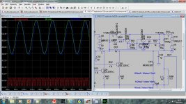
To cut that discussion(one sided) down, here is simulation of the Capacitance multiplier designed for 100 W OPS.
The simulation shows input of the 50 V(yellow) with 100 Hz 2 V pp superimposed, input after 0.1 ohm and on the 4700uF(blue) and output from the C multiplier(red). Output power is 100W on 8 ohm load. With the 2 V pp at the input of the C multiplier, output shows no saturation(Vce never drops below Vbe) and only 20 mV pp of the 100 Hz fluctuation.
If someone thinks that this is a crap please explain with an argument and a simulation.
dado
Attachments
I don understand your figures at all! What is 0.1 ohm at the input? 50v with 0.1 ohm is 25000Watt. And you write the output is delivering 100watt at 8ohm. Huh? 8 ohm at 50volt gives 333watt. So what is it?To cut that discussion(one sided) down, here is simulation of the Capacitance multiplier designed for 100 W OPS.
The simulation shows input of the 50 V(yellow) with 100 Hz 2 V pp superimposed, input after 0.1 ohm and on the 4700uF(blue) and output from the C multiplier(red). Output power is 100W on 8 ohm load. With the 2 V pp at the input of the C multiplier, output shows no saturation(Vce never drops below Vbe) and only 20 mV pp of the 100 Hz fluctuation.
If someone thinks that this is a crap please explain with an argument and a simulation.
dado
very good, and why must that ripple so low. What is the advantage above using that input with 2V ripple. The disadvantage using this circuit is that the average voltage is lower and power loss.
Actually it is similar to the ripple on the C15(cap connected to the base of the Q30), but at much higher current. You can use small capacitance(470uF in this case) and get it multiplied and thus better filtering with less cost(transistors are cheaper then big elcos). In my amp I use separate C multipliers for input stage and output stage. One very important aspect of this is that all multipliers are very close to the stages, input or output.
dado
I don understand your figures at all! What is 0.1 ohm at the input? 50v with 0.1 ohm is 25000Watt. And you write the output is delivering 100watt at 8ohm. Huh? 8 ohm at 50volt gives 333watt. So what is it?
I am realy lost with you, and you are professor at University?
I am realy lost with you, and you are professor at University?
So try to explain then, can you?
I understand how the circuit works. You can even make the ripple zero by putting a zener from base to ground. Driving stages needs ripple free supply but the needed curent is low so a resistor and zener only will fullfil the taske. The output stage doesnt need ripple free supply so why you do this?Actually it is similar to the ripple on the C15(cap connected to the base of the Q30), but at much higher current. You can use small capacitance(470uF in this case) and get it multiplied and thus better filtering with less cost(transistors are cheaper then big elcos). In my amp I use separate C multipliers for input stage and output stage. One very important aspect of this is that all multipliers are very close to the stages, input or output.
dado
(transistors are cheaper then big elcos)
Much different story in the late 1980s, even today, A1244/C3263 are not exactly cheap.
Ever simulated the power supply of a Nak PA-7 ?
(a single 700VA toroidal for 2 channels, 60Vac secondaries, 4 x 33.000uF lytic bank)
I understand how the circuit works. You can even make the ripple zero by putting a zener from base to ground. Driving stages needs ripple free supply but the needed curent is low so a resistor and zener only will fullfil the taske. The output stage doesnt need ripple free supply so why you do this?
No you don't.
What has to be simulated? One can also just think. Even when the transistors cost nothink, a cap is better. The circuit you called cap multiplier, is known as old as the valve time but to reduce ripple further a zener is placed from basis to ground. However what is the use for the endstage? Good endstages doesnt need ripple free suply and with that circuit you lost power. Hilaric.Much different story in the late 1980s, even today, A1244/C3263 are not exactly cheap.
Ever simulated the power supply of a Nak PA-7 ?
(a single 700VA toroidal for 2 channels, 60Vac secondaries, 4 x 33.000uF lytic bank)
No you don't.
Look to the conductance matrix of a transistor and find out that the conductance from colector to emiter is practically zero.
One can also just think.
The latest Dartzeel 458 monaurals each have a 2KVA toroidal with a huge oversized core, 4.5 times the nominal power rating.
Mr Hervé Delétraz is from your turf, the things cost 150K a pair, you must find that Hilarious too.
Does it use a C multiplier? If yes its hilaric, if not, big transformer is may be overkill often done in expensive amps to overwhelm foolisb customers. At least it happens 1 time in the past that a manufacturer put concreet in the amp to make it heavy=goodThe latest Dartzeel 458 monaurals each have a 2KVA toroidal with a huge oversized core, 4.5 times the nominal power rating.
Mr Hervé Delétraz is from your turf, the things cost 150K a pair, you must find that Hilarious too.
- Status
- This old topic is closed. If you want to reopen this topic, contact a moderator using the "Report Post" button.
- Home
- Amplifiers
- Power Supplies
- Power Supply Resevoir Size