http://www.diyaudio.com/forums/atta...727278t-power-supply-resevoir-size-simple.pngHere we go
This is the way I approach it now.
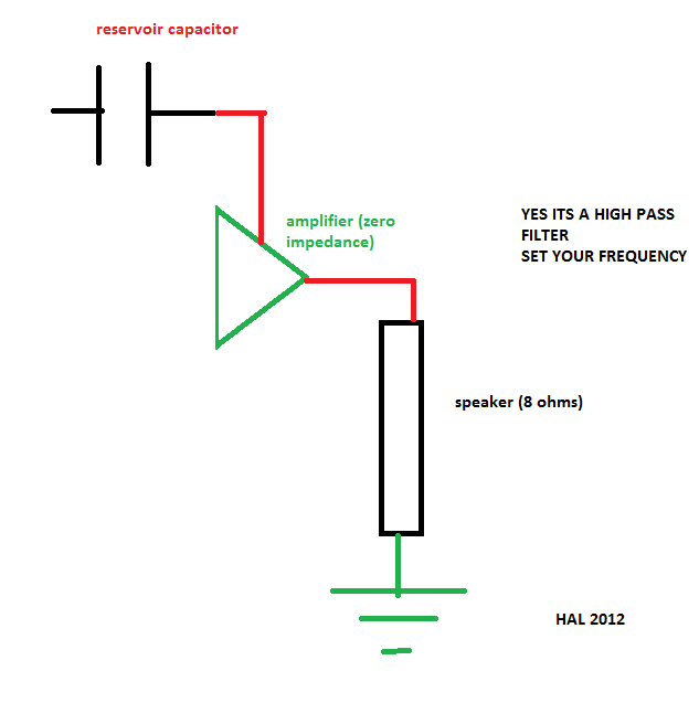
It is a filter.
This filter should not interfere with the action of the NFB.
This filter should not be the dominant roll-off of the bass frequencies. The input filter does that.
I set the pole of the reservoir capacitance at least a full octave lower than the input filter.
And I am back and looking quite brown compared to my usual complexion. Extended = 50days. I got back a little early. I was missing you all!
Last edited:
See the post after yours (i.e. post 372).
It shows that it's exactly as I've been saying all along:
The rail CURRENTS _ARE_ the signal, non-inverted, and they come from the capacitors.
Each rail does one polarity. So the currents look like a push-pull version of the signal.
The rail VOLTAGE just sags a little when the transistors open up, to let just the right amount of current out of the caps to create the load voltage.
Edit: It looks like the current for the negative rail cap (fC5) somehow got inverted, in the first image in post 370 (the 1600 uF version of the zoomed drum strike).
Cheers,
Tom
Yes there are some amplifiers that use this technique to drive the load
(And I still haven't even gotten to the decoupling caps, yet!)
Like a baby waiting for candy

 was wondering about you
 No worries, Nico, I'm pleased that people are positive about where this is going!Sorry I meant Frank
Thanks,
Frank
Frank,
Good insight. That is the trade-space that needs to be quantified.
The voltage goes back up, a few seconds after that sim ends, by the way. But that points out a possible criterion for choosing the reservoir capacitance: They have to be large-enough to have enough charge to supply a sustained "short term" demand, i.e. at least until the next charging pulse, but also need to be small-enough that a) they don't drag the voltage too low for a worst-case burst between charging pulses, and b) they aren't so large that they can blast out a LOT more current than a charging pulse can supply, because then, if they're unlucky with the size and timing of the demand versus the size and timing of the charging pulses, they could just continue to force the rail voltage lower and lower. That's part of the equation we need!
This looks like a probability problem, too. What fun! (groan).
ESR and ESL play a role there, too, both those of the capacitors and those of the interconnects on both sides of them. And the transformer and rectifiers will probably need to be able to supply extra-big charging pulses, sometimes.
Cheers,
Tom (going to bed now)
I applaud the analytical approach, but isn't getting into probability taking things too far? My conclusions based on doing the engineering math, simulation, and listening are, to minimize the influence the power rail can have on the output, you need 3 things:
1) rails 20V higher (my rule of thumb, yours may vary) than the maximum output swing so that the rails can sag under load but still be comfortably above the maximum output voltage;
2) sufficient capacitance to handle the maximum specified output current (your earlier post showed how to calculate that.) Any more is of dubious benefit, and certainly increases cost. So do the math, figure out how many Farads you need, then apply whatever margin you like. My rule of thumb on the margin would be 20%, remember we're talking about peaks.
3) a design with high PSRR.
That gets you 95% of the way there. The next 4.5% is paying attention to low ESR in the capacitance bank and minimizing inductance in the power leads.
I agree with you, mightydub, rules of thumb get you a long way down the path to the good stuff, top notch sound. But, in my experience, it's that last 0.5% where the real battle is, that's the area where everything measures beautifully, but it doesn't turn you on, vs. sound that makes all the question marks in your head go away ...That gets you 95% of the way there. The next 4.5% is paying attention to low ESR in the capacitance bank and minimizing inductance in the power leads.
Frank
1) rails 20V higher
Transformers must be cheap overthere.
That's just about equivalent to specifying a 180W into 8ohms, (53.7Vpk & +-60Vdc supply rails) amplifier and never using it @ >=100W into 8ohms, (40Vpk).1) rails 20V higher (my rule of thumb, yours may vary) than the maximum output swing so that the rails can sag under load but still be comfortably above the maximum output voltage;
What a waste of resources and design effort.
Most "Rule of Thumb" guidelines will do far better than applying "-20V" to the supply rails!
If one were working with a 60W amplifier (+-36Vdc supply rails) then the "-20V" rule becomes silly.
Last edited:
But, that 20V does appear at a simple glance to be what's needed. For the sake of consistency, in comparing like with like, I used and adapted Tom's last posted circuit, for the moment "ditched" his fancy capacitor model because there were some spurious glitches appearing in the sim:

The PS rails with no load, the output stage disconnected, sit at 82V. Then, reconnected and idle current flowing, the rails drop to 71V. Finally, add a rather vicious, constant load of summed 20Hz, 635Hz, and 20,000Hz (635 midway point ...) sine waves which peak just below clipping, and see what happens to the rail:

Sags right down to 59V in less than half a second -- that 20V margin doesn't look that bad after all now ...
And what happens to the output with droopy rails? A nice bit of clipping ...

Frank
The PS rails with no load, the output stage disconnected, sit at 82V. Then, reconnected and idle current flowing, the rails drop to 71V. Finally, add a rather vicious, constant load of summed 20Hz, 635Hz, and 20,000Hz (635 midway point ...) sine waves which peak just below clipping, and see what happens to the rail:
Sags right down to 59V in less than half a second -- that 20V margin doesn't look that bad after all now ...
And what happens to the output with droopy rails? A nice bit of clipping ...
Frank
Fas,
what is the supply rail voltage when the amplifier is delivering full power?
I ask because the 9Volts lost from no load to quiescent load seems enormous, compared to "normal" power amp PSUs. I'd expect to see the supply rails of a 100W into 8r0 amplifier sagging to ~+-45Vdc @ full powwer, from a quiescent of ~+-50Vdc and zero load of +-50.5Vdc. This is 0.5V sag, cf. your 9V sag.
Remember, at the moment, I'm just using Tom's transformer parameters as is, I haven't looked closely at how "reasonable" they are ...Fas,
what is the supply rail voltage when the amplifier is delivering full power?
I ask because the 9Volts lost from no load to quiescent load seems enormous, compared to "normal" power amp PSUs. I'd expect to see the supply rails of a 100W into 8r0 amplifier sagging to ~+-45Vdc @ full powwer, from a quiescent of ~+-50Vdc and zero load of +-50.5Vdc. This is 0.5V sag, cf. your 9V sag.
At idle, the output stage dissipates about 13W, 5W in Q3 and Q4, 1.6W in Q1 and Q2. Then, driving with a pure 1kHz tone to just clipping, the voltage sag is stable at 57V. Voltage p-p is just over 100V, and power dissipated in the 4R load is 320W.
Frank
320W into 4r0 is 50.6Vpk (101.2Vpp).
That is a reasonable unclipped maximum from a loaded PSU supplying +-57Vdc, i.e. 6.4Volts of losses through the amplifier. Particularly when the 57Vdc is actually modulated with the PSU ripple (what is the loaded PSU ripple when delivering maximum power?). This leaves the Vsupply minimum ~55V, or really a 4.4Volts loss through the amplifier.
Can you change the transformer data/model to more realistically mimic what a "normal" transformer shows when unloaded/loaded? Maybe Gootee could supply data.
Last edited:
This is where the action is. The transformer, as "supplied", has secondaries looking like this at full power, 320W into 4R:Can you change the transformer data/model to more realistically mimic what a "normal" transformer shows when unloaded/loaded? Maybe Gootee could supply data.

Nasty looking, eh? But how realistic ...?
If I back off to idle, things improve somewhat ...

Then, disconnect all load to the rails, and we get the textbook result:

Interesting times ahead ...
Frank
Last edited:
Sorry, ignore that figure of 82V I posted earlier for no load conditions. As Andrew pointed out, there was something awry there, and it turned out to be a combination of me being confused with a result taken under different conditions, earlier on, and not allowing sufficient time for the voltage to settle. A much more accurate value is a touch under 73.4V, so the transformer model is most likely to be of good accuracy ...
However, that doesn't change the main story that significantly, on the need for close to 20V "safety margin": 73.4V no load, 57V for full power, no clipping ...
Frank
However, that doesn't change the main story that significantly, on the need for close to 20V "safety margin": 73.4V no load, 57V for full power, no clipping ...
Frank
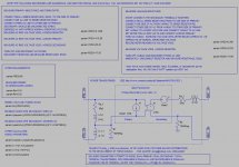
Here is the transformer model.
The only transformer models I have made are for transformers with around 22-30V outputs, since those are the only ones I measured (see measuremnt steps in model image).
So what is being used in the simulations is this model, but with a much higher input voltage amplitude than normal, in order to make the output voltage higher.
I just noticed, too, that the inputs and outputs are labeled. When identical labels are used in spice, those points in the circuit are joined, as if with a wire. So in the simulations so far, the secondaries of the two transformers have been in parallel. I will change that and see if it makes a difference, and will post a new overall model with the correction.
P.S. Frank, I lowered the input voltage to 321 V, to get an unloaded output voltage of roughly 71.136 Volts.
Cheers,
Tom
Attachments
Last edited:
- Status
- This old topic is closed. If you want to reopen this topic, contact a moderator using the "Report Post" button.
- Home
- Amplifiers
- Power Supplies
- Power Supply Resevoir Size