I understand you Nico. When I started building amps, I started with transistor amps and messed around with them a lot. At that time yes I can say that isolating the voltage section of the amplifier used to make the amplifier open up and ease up. Then I moved to Chip amps such as TDA and STK. STK used to isolate with 100 Ohm and 100uf.
Will continue the story....
Will continue the story....
................In other words should we spend less on mega farads power supplies when 4700 uF (or less) will do and pay more attention to the front end driver stage power supply ?
That's very possible (and I'm not really a fan of huge values of C in PSU's) and yet I can't help but feel its how everything in a complete amp design comes together that really counts.
[If you saw the PSU I used (and still use) for initial amp development you would laugh. It's an 18VA (yes, no 0 on the end) 15-0-15 tranny feeding 4700uf caps. It's SC proof up to point and hasn't enough welly to damage outputs and yet still allows an amp to be driven to moderate levels on music. That's where the lateral amp started its life and where it first started to sound so good that I just knew I had to build it as a successor to the blameless I was then using]
If I were building the lateral amp again I might look at higher separate rails for the front end which would be easy at such low currents. A voltage doubler and zener would be more than adequate I think. Would it be as good though.
It's and interesting subject but I don't think there are hard and fast rules, certainly no magic formula.
Very interesting subject! I hear all the time people saying monsters power supply (capacitance) will sound better... Will they? Well I try long time ago when I was building some of the NXV200 from Aussie amplifiers a big and strong power supply 80.000uf per rail, the sound was very good, but then I try with just 20.00uf per rail to see if there was so much difference. The result was that with 20.000uf the amp sounded faster (if that is a definition). from then till now when I build an amp (class A/B) let's say from 50 to 100 watts RMS per channel I use no more than 20.000uf per rail (using like 6.800uf caps values) with excellent results. I just concentrate in the quality of the capacitors in my case I use Mundorf audio grade 125c. I did try many brands before, but my first choice is Mundorf audio grade caps for their quality and sound.
Hugh, AndrewT, Carlos, Andrej, Homemodder, Michael, Sakis, lets have views from all the old other experienced guys, because you are past speculation you have tried stuff that worked, tell us what worked and why you think it was a better solution.
I promise I will try out some stuff practically from what is disclosed here in the next few weeks and report my findings, maybe we can establish some audio rule of thumbs that can be made applicable. Maybe what our friend Lancile has to say is very important it is quality in stead of quantity, low impedance, high ripple current, high temp, etc.
I promise I will try out some stuff practically from what is disclosed here in the next few weeks and report my findings, maybe we can establish some audio rule of thumbs that can be made applicable. Maybe what our friend Lancile has to say is very important it is quality in stead of quantity, low impedance, high ripple current, high temp, etc.
Last edited:
Larger banks of capacitors takes longer time to reform.
The connection distance from the capacitor bank to the amplifier.
The cooling of the capacitors.
The quality of the capacitors. (the purity in all used materials)
The are some information of this here:
Capacitor Characteristics
Power supply considerations here:
http://www.profusionplc.com/images/data sheets/ecf10-demo.pdf
This has the makings of a Really Great Thread, Nico.
Only tommy1000 seems to have touched on the inductance of the power and ground connections between the reservoir caps and the active devices they are supposed to supply.
I believe that decoupling caps, across (and very close to) each and every active device's power/gnd connections, are even more important than the reservoir caps (or, at least they're at least as important).
Why? Transient Response accuracy, which equates to proper phase and time alignment of all frequency components, and is probably responsible for all of the good sound qualities and nuances that obviously cannot be estimated by measuring simple "distortion" (THD+N, IMD, etc) of the Steady-State Response. (Accurate transient response also prevents things like overshoot and ringing. If you purposely slightly-misalign the phase angles of the Fourier components of a square wave, even just in a monotonically-frequency-dependent way, you can get what looks EXACTLY like overshoot and ringing after the leading edge of the square wave. It makes sense, eh?)
Rail inductance makes it impossible for the reservoir caps to do the Transient Response accurately. And if they are forced to try, large rail voltage disturbances will result from V = L di/dt, from the inductance L of the supply and ground rails.
Are ripple and other rail-voltage disturbances "bad" for sound quality? It depends on the PSRR (which usually gets worse with higher frequency, et al). Obviously, ripple + L(di/dt) disturbances COULD be bad for sound quality. After all, all types of transistors are simply voltage-controlled or current-controlled RESISTORS, i.e. electronically-controllable "current valves". (And "the signal path" that we actually hear is the current, which goes from the power supply reservoir caps and the decoupling caps, through the power transistors, to the speakers, and back again.)
Anyway, we go to a lot of effort to accurately set the resistance of the transistors, according to the input signal, but the actual current that flows from the caps to the speakers then ALSO depends on the voltage across the transistor, since I = V/R.
So unless your circuit is tracking the power supply ripple and adjusting its control of the transistors to correct the resistance it sets them to, at each instant, based on the variations of Vsupply (as seen at the transistor), then the current (I) will not be the V/R that was intended, but would be (V+Vripple+L(di/dt))/R. Feedback of the output signal should also take the power supply voltage variations into account, but not "directly"; basically it's after the problem is already occurring. So it's probably much better to avoid the supply rail and ground rail voltage disturbances ahead of time.
It all boils down to being mindful of the power supply characteristics, AT the power transistors' connections (i.e. NOT back at the output of the PSU, which, for transient response, might as well be miles away if there are several inches or more of supply and ground conductors).
So we can look at that in both the frequency domain (is the impedance seen, when looking from the point of view of right AT each transistor's local power supply connections, staying low-enough, up to a high-enough frequency?) and the time domain (possibly mostly in terms of: a) is there enough local capacitance for worst-case transient current demands to be met accurately-enough and with low-enough induced voltage disturbances? b) what is the maximum inductance that can be tolerated in the local capacitance's connections to the device, to still achieve (a)?, and c) can the distant reservoir caps supply everything else accurately-enough?).
Anyway, there are relatively-easy ways to calculate everything I have mentioned. And the example calculations I have done so far do point to specific physical layout characteristics that should be considered, possibly much more than they usually seem to be, mainly in terms of getting enough capacitance close-enough to where it's needed, so that the total inductance is low-enough.
I haven't finished my work on that, yet, but so far it appears that it's surprisingly easy to not do it well-enough, which could be one of the reasons that some amps that measure extremely well in terms of THD and IMD just don't sound as wonderful as some might think that should imply.
If anyone is interested, here are most of the posts where I started trying to develop the equations for minimum capacitor size and maximum tolerable connection length:
http://www.diyaudio.com/forums/powe...lm-caps-electrolytic-caps-23.html#post2806854
http://www.diyaudio.com/forums/powe...lm-caps-electrolytic-caps-26.html#post2822959
http://www.diyaudio.com/forums/powe...lm-caps-electrolytic-caps-31.html#post2835052 (PSU impedance, at the load, AS LOW AS YOU WANT: parallel copies of supply and ground rails, from each reservoir cap all the way to each decoupling cap and the point of load)
http://www.diyaudio.com/forums/powe...lm-caps-electrolytic-caps-32.html#post2835300
http://www.diyaudio.com/forums/powe...lm-caps-electrolytic-caps-33.html#post2841513 (downloadable LT-Spice model files)
http://www.diyaudio.com/forums/powe...lm-caps-electrolytic-caps-38.html#post2902690 (very interesting, about reservoir caps)
http://www.diyaudio.com/forums/power-supplies/208579-30vdc-10a-psu.html#post2942537
Cheers,
Tom
Tom,
About two years ago MiiB (Michael) and I was exchanging ideas on an amp design and he came forward with a PCB layout that had a reservoir cap of 10000uF between each power device. i.e. there was a large cap sitting a few mm from the active device.
I thought this was quite a novel idea at the time. I have not tried it in reality but it seems to tally with what you are promoting here Tom. It may not only be what is in the power supply but how it is distributed that makes the difference.
Yes, I believe that the distribution is extremely important and your friend was on the right track.
One improvement that now seems obvious would have been to use several smaller caps in parallel, in place of each 10kuF cap.
For large capacitance values, paralleling N smaller caps is almost always much better, especially if their connections are also paralleled (i.e. kept separate) as much as possible. Then you get 1/N x inductance, 1/N x ESR, and N x capacaitance, all at the same time.
Also note that I was doing everything I mentioned above with the idea that most DIY people can not use six-layer PCBs with real power and ground and signal and guard planes. But if we use many smaller reservoir caps in parallel, AND have a pair of SEPARATE parallel power and ground conductors for EACH reservoir cap, that run all the way to the active load, and also have one of the (multiple parallel) decoupling caps across each of them, on the load end, and we replicate that as many times as we can with the space available, then we can get PSU and transient performance that is as good or better than what we could get with power and ground planes. (The reason it could be better is that the designer of the planed version might not be able to arrange his caps so that all their currents take separate paths, on the power and ground planes, which would cause mutual inductance and the maximum inductance reduction due to paralleling would not occur. Or, he could be unable to distribute multiple parallel power or ground connections to each of the planes, which would have a similar effect.)
For my next DIY power amp project, I am envisioning multiple ribbon cables for the power and ground rails
Hugh, AndrewT, Carlos, Andrej, Homemodder, Michael, Sakis,...... .
Where is AndrewT ? Its been nearly a month now since he was last on here.
Thanks for the info Tom, I think I will implement the idea of distributed power "supply" with a star arrangement which would effectively remove modulation between power lines to different areas as well.
One is inclined to think of a power supply as a separate self contained unit and normally design it as such. Looking inside 9/10 amps the power supply sits in the middle of the box instead of being distributed to areas as needed.
One is inclined to think of a power supply as a separate self contained unit and normally design it as such. Looking inside 9/10 amps the power supply sits in the middle of the box instead of being distributed to areas as needed.
Nico,
I began using onboard power supplies, separate full wave rectification and filter bank for each rail, several years back. This keeps track lengths very short. I also use two filter caps per rail, with 0.15R resistors between them on both terminations. This means one cap takes the aggressive charge pulse while the other cap, with much reduced and longer duration charge cycle, handles earth return for the speaker voice coils.
I believe the amps sound better as a result. My FetZilla design, done with Greg Peters and Mike Meares, uses this principle, and all seem to agree it sounds damn good, with subjective power way beyond its rating.
Cheers,
Hugh
Thanks Hugh, I appreciate your contribution. I have followed the Fetzilla thread for a long while and what Hugh says makes sense also. So what do we have so far:
Caps should not be too bulky. Should be distributed where current is needed or voltage need be held constant, tracks should be kept short to what it is sourcing, some series resistance on the incoming lead act as ripple filtering.
It is getting interesting. What difference would it make if rectifiers are close to caps or should one try and mount them separately. The leads to the caps would act as both series resistance and inductance. So lets say one runs a star connection from the diode block to the various on board smoothing caps, and calculate the cap value for the job it needs to do.
Hi to all DIY friends 
Nico it's good that a discussion about amp PSU-s is opened from time to time, to share experiences and to enlighten certain practical guidelines for DIY-ers to make better amps.
From mine past amps I learned that separate PSU rails for a front-end/output stage is a way better solution, simply because relation between front-end and output stage is similar to Beauty and the Beast like. PSU's impedance/current capability demands for the two are so apart from each other that the best solution is to supply them separately and than allow them to dance together.
In short, my practical instructions for amp's linear PSU would be:
- 4 times VA to Wrms rating for the mains transformer, over current capability (low impedance, core magnetic reserve) to fast charge the caps
- fast/ultra fast on amp PCB rectifier pairs, separate for front-end and output (4 all together)
- 2000 uF/A capacitance bank in my SSA/CSA case it means 2200 uF/rail for front-end and 22000 uF/rail for output stage (100 Wrms/8 ohm), all caps on amp PCB mounted
- as short as possible PCB tracks to the outputs
- on PCB two star grounds (one front-end PSU GND, other output stage PSU GND) connected together with 5-10 mm track, prevents interference between high/low currents in each GND
- quality of the electrolytic caps is a must
- decoupling with 1 uF/0,1 uF, especially in splitting/ending points on PCB
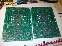
Example is CSA PCB in attachment. Nothing new but just one more practical example from the real build.")
Nico it's good that a discussion about amp PSU-s is opened from time to time, to share experiences and to enlighten certain practical guidelines for DIY-ers to make better amps.
From mine past amps I learned that separate PSU rails for a front-end/output stage is a way better solution, simply because relation between front-end and output stage is similar to Beauty and the Beast like. PSU's impedance/current capability demands for the two are so apart from each other that the best solution is to supply them separately and than allow them to dance together.
In short, my practical instructions for amp's linear PSU would be:
- 4 times VA to Wrms rating for the mains transformer, over current capability (low impedance, core magnetic reserve) to fast charge the caps
- fast/ultra fast on amp PCB rectifier pairs, separate for front-end and output (4 all together)
- 2000 uF/A capacitance bank in my SSA/CSA case it means 2200 uF/rail for front-end and 22000 uF/rail for output stage (100 Wrms/8 ohm), all caps on amp PCB mounted
- as short as possible PCB tracks to the outputs
- on PCB two star grounds (one front-end PSU GND, other output stage PSU GND) connected together with 5-10 mm track, prevents interference between high/low currents in each GND
- quality of the electrolytic caps is a must
- decoupling with 1 uF/0,1 uF, especially in splitting/ending points on PCB
Example is CSA PCB in attachment. Nothing new but just one more practical example from the real build.
Attachments
Andrej, thank you for your most informative comments, it would seem that splitting the power supply up is becoming a confirmed choice of some of our experienced members.
Hugh, in my one comment I mentioned your simple but effective means of decoupling of front- and back-end of your earlier amplifiers by means of a diode and resistor/capacitor filter.
Do you still subscribed to this method for the same reasons Andrej mention above, or have you discarded it because there is no sonic benefit.
Andrej, do I understand you correctly that you use two completely different supplies on the front and back end.
Do they share the same secondaries of the transformer or are they actually different transformers, which of course is more expensive but probably makes sense or maybe the diodes block the power modulation effectively.
Do they share the same secondaries of the transformer or are they actually different transformers, which of course is more expensive but probably makes sense or maybe the diodes block the power modulation effectively.
Andrej, do I understand you correctly that you use two completely different supplies on the front and back end.
Do they share the same secondaries of the transformer or are they actually different transformers, which of course is more expensive but probably makes sense or maybe the diodes block the power modulation effectively.
Four completely separate secondary windings, two 52 Vac for the front-end and two 45 Vac for the output. Each winding is connected to full wave rectifier bridge.
- Status
- This old topic is closed. If you want to reopen this topic, contact a moderator using the "Report Post" button.
- Home
- Amplifiers
- Power Supplies
- Power Supply Resevoir Size